Indoor air purifying device

A technology for indoor air and purification devices, applied in the field of air purification, can solve the problems of poor air purification effect, low packing density of flat membrane, poor separation effect, etc., and achieve compact and compact equipment, high mass transfer efficiency and low energy consumption Effect

Inactive Publication Date: 2007-10-24
SOUTH CHINA UNIV OF TECH
View PDF1 Cites 7 Cited by
  • Summary
  • Abstract
  • Description
  • Claims
  • Application Information

AI Technical Summary

Problems solved by technology

This air purification technology adopts microporous membrane separation, the separation mechanism is molecular sieve, one pore size can only separate one VOCs gas, the separation effect is very poor, and the flat membrane packing density is small, the mass transfer efficiency is low, and the air purification effect is not good.

Method used


Image

  • Indoor air purifying device
  • Indoor air purifying device
  • Indoor air purifying device

Examples


Embodiment 1

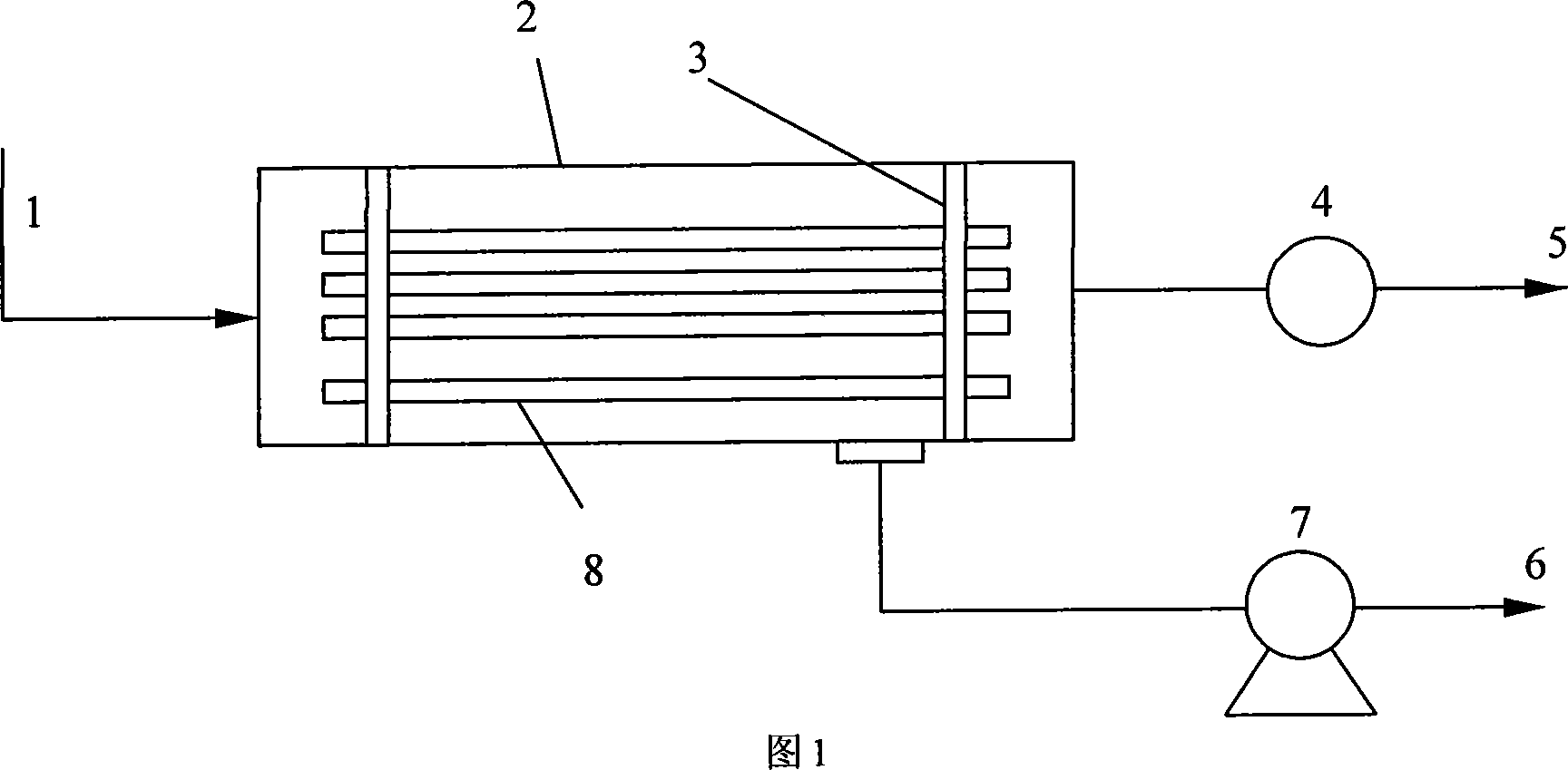
[0024] The indoor air purification device of the present invention is shown in Figure 1, and the device includes an air inlet 1, a housing 2, an epoxy resin head 3, a fan 4, an air outlet 5, a VOCs outlet 6, a vacuum pump 7, and a hollow fiber 8. The air inlet 1 is connected to one end of the housing 2, the housing 2 is connected to the vacuum pump 7, and the volatile organic compound outlet 6 is connected to the vacuum pump 7; the fan 4 is connected to the other end of the housing 2 and is connected to the air outlet 5 The epoxy resin head 3 seals the hollow fiber 8 into a shell side and a tube side, the hollow fiber 8 and the head 3 are sealed and airtight, and the space between the head 3 and the shell 2 is also sealed and airtight; Driven by the fan 4, the indoor air enters the shell 2 through the air inlet 1 and flows through the hollow fiber tube, the VOCs in it enter the shell side through the wall of the hollow fiber, and the clean air after removing the VOCs flows out ...

Embodiment 2

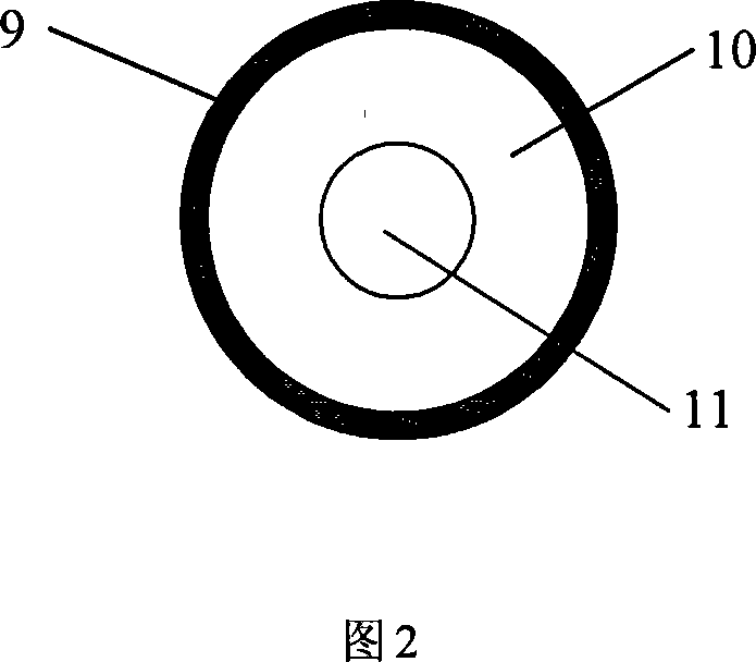
[0027] The specific structure of the hollow fiber of the present invention is shown in Figure 2, the dense skin layer 9 is located outside the hollow fiber, and the porous support layer 10 is located inside the hollow fiber. As can be seen from Figure 2, the indoor air goes through the pipe 11, and the porous support layer 10 of the hollow fiber is a porous support body with a thickness of 100-200 μm, including polyvinylidene fluoride (PVDF), polyetherimide (PEI) , any one of polyacrylonitrile (PAN), polypropylene (PP), polysulfone (PSU) etc., its pore diameter is 0.4-2.0 μm; the thickness of the dense cortex 9 is 0.2-5 μm, non-porous, and its material includes poly Any of dimethylsiloxane (PDMS), polyether block amide (PEBA), etc.

Embodiment 3

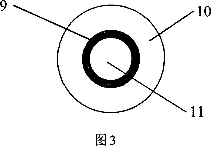
[0029] Another structure of the hollow fiber of the present invention is shown in FIG. 3 , the dense skin layer 9 is located inside the hollow fiber, and the porous support layer 10 is located outside the hollow fiber. As can be seen from Fig. 3, the indoor air goes through the pipe 11, and the porous support layer 10 of the hollow fiber is a porous support body with a thickness of 100-200 μm, including polyvinylidene fluoride (PVDF), polyetherimide (PEI) , any one of polyacrylonitrile (PAN), polypropylene (PP), polysulfone (PSU) etc., its pore diameter is 0.4-2.0 μm; the thickness of the dense cortex 9 is 0.2-5 μm, non-porous, and its material includes poly Any of dimethylsiloxane (PDMS), polyether block amide (PEBA), etc.


PUM

PropertyMeasurementUnit
pore sizeaaaaaaaaaa
thicknessaaaaaaaaaa
thicknessaaaaaaaaaa

Abstract

The invention relates to an indoor air purification device that comprises the air inlet, shell, air blower, air exhauster, vacuum pump and volatile organic compound outlet, with hollow fiber inside the shell, epoxide resin roll end separating the hollow fiber into shell and tube, forming into a tubular heat exchanger, the said air inlet connected with one end of the shell, which connects with the vacuum pump, volatile organic compound outlet connected with the vacuum pump, the other end of the wind blower connected with the other end of the shell and connected to the wind blower, indoor volatile organic permeated into the tube and the shell under the drawing force of the vacuum pump, exhausting the said volatile organic compound through its outlet. It can effectively remove most of the volatile organic compound with efficiency over 80%. It is more efficient, energy economical and environmental protective.

Description

technical field [0001] The invention relates to an air purification technology, in particular to a technology and a device for purifying indoor air by using hollow fibers. Background technique [0002] A good indoor air environment is crucial to human health. The energy crisis in the 1970s and the development of construction and related technologies led to increased building airtightness, reduced operating energy consumption, and reduced fresh air volume in buildings. On the other hand, a large number of new building decoration materials were used, some of which emitted harmful gases. Therefore, people who live and work in modern buildings for a long time often show a series of morbid reactions: headache, drowsiness, nausea and runny nose, etc., which is called "sick building syndrome". According to reports, the direct economic loss caused by poor indoor air quality in the United States is as high as more than 40 billion U.S. dollars every year, and 24 million deaths in the...

Claims


Application Information

Patent Timeline
Patent Type & Authority Applications(China)
IPC IPC(8): B01D53/22B01D46/54
Inventor 张立志
Owner SOUTH CHINA UNIV OF TECH
Why Eureka
Try Eureka