Roller type cavity die extrusion molding method

A technology of extrusion forming and rollers, which is applied in the direction of metal extrusion, metal extrusion dies, indenters/punches, etc., can solve the problem of inability to complete the transverse and longitudinal sections of workpieces, increase the limit value of plastic deformation strength, and increase the overall Machine equipment tonnage and other issues, to avoid heat accelerated wear, prolong life, prolong the effect of mold life

Inactive Publication Date: 2009-07-01
ZHONGBEI UNIV
View PDF5 Cites 2 Cited by
  • Summary
  • Abstract
  • Description
  • Claims
  • Application Information

AI Technical Summary

Problems solved by technology

[0003] 1. The traditional method of direct extrusion molding of bar material as a blank is a traditional extrusion method that uses extrusion to achieve the dual goals of reshaping and improving performance. It cannot extrude thin-walled plates because of fast heat dissipation, and the required pressure The tonnage of the machine is large, the life of the mold is low, it is rigid sliding friction, and the wear is severe; the extrusion end should be cut off as a waste head, and the material utilization rate is low
This kind of traditional extrusion cannot complete the forming of flat and circular metal parts with variable cross-sections that vary in transverse and longitudinal cross-sections.
[0004] 2. The traditional method of upsetting and pressing in the thickness direction of a large flat plate by relying on the wedge movement is that the blank is a thick plate, extruded into a cone plate, and then extruded by a mold
Rolling is to set various ring-shaped cross-section passes on the roll in the radial direction, and roll out various profiles with continuous and equal cross-section shapes, while roll forging is to set various shapes of cavities along the axis on the roll, forging out Parts with intermittent and cavity shapes; rolling and roll forging are characterized by active biting and compression deformation by rolls or rolls, so that the blank bears three-dimensional compressive stress in the deformation zone, thereby increasing the strength limit of plastic deformation The value (deformation resistance), reflected in the macroscopic view, is to increase the bending and torsion deformation force of the roll or roll to the outside, and the external force required for forming is relatively large, so increasing the force on the mold (roller) will also make the mold (roller) ) is correspondingly reduced in service life, and at the same time increases the tonnage of the complete machine and increases energy consumption

Method used


Image

  • Roller type cavity die extrusion molding method
  • Roller type cavity die extrusion molding method
  • Roller type cavity die extrusion molding method

Examples


Embodiment Construction

[0035] The present invention will be further described below in conjunction with the accompanying drawings. (Taking flat variable cross-section metal parts as an example)

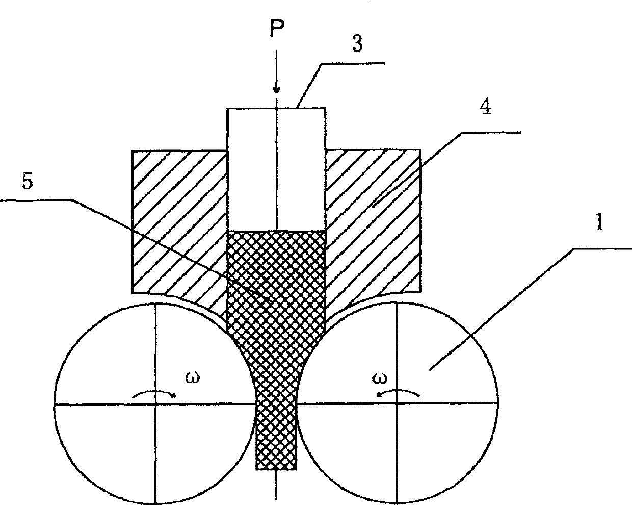
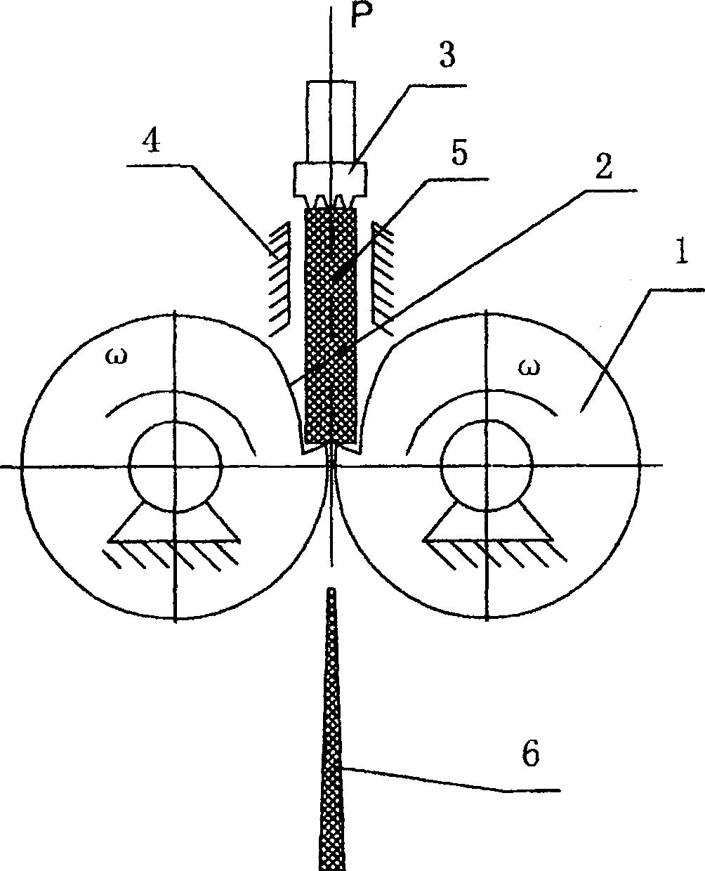
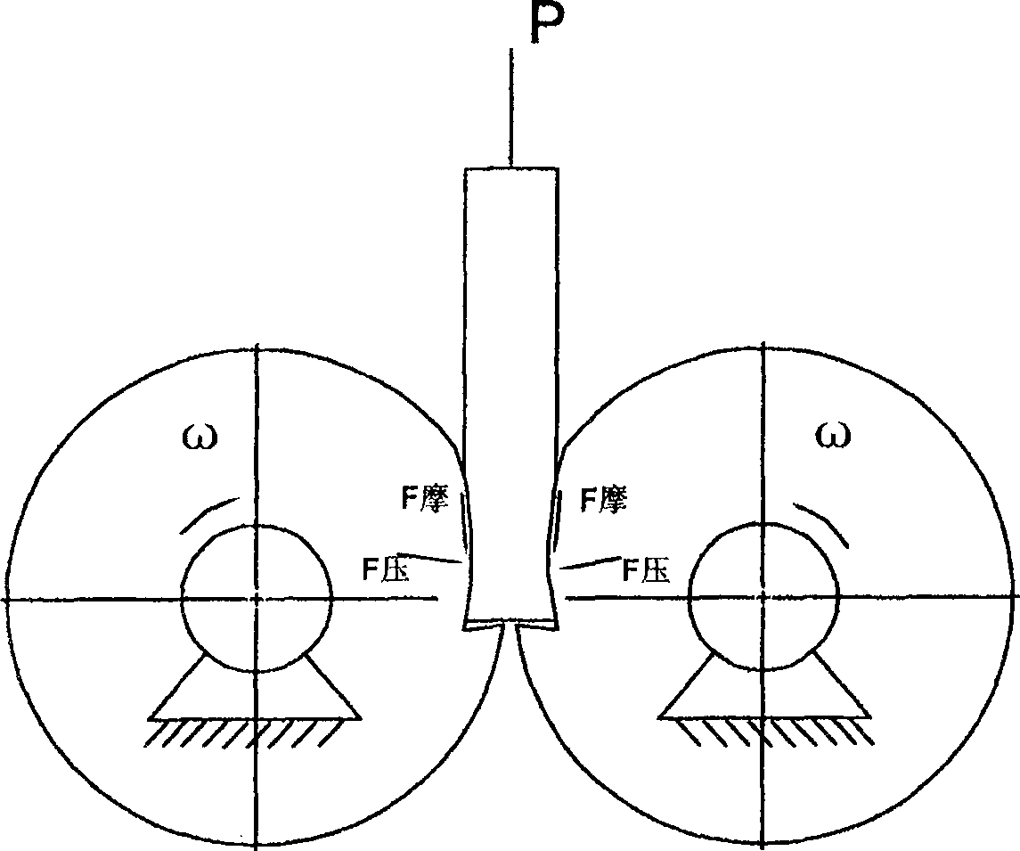
[0036] figure 1 and figure 2 Shown is a schematic diagram of a roller-type die extrusion forming method of the present invention. A roller-type concave die extrusion forming method adopts a pair of rollers 1, the cavity 2 of the concave mold is opened on the circumferential surface of the two rollers along the axial direction, and at the same time, there are pushing rods 3 and extrusion rods at the entrance of the roller blank. Press cylinder 4, the forming process of its part is:

[0037] (1) The blank 5 is filled in the extrusion cylinder, and the push rod exerts a thrust P on one end of the blank, and the blank is pressed and pushed, and at the same time plays a role of alignment, and the end of the push rod is perpendicular to the auxiliary center line of the two rollers;

[0038] (2) The push rod...


PUM


Abstract

The invention relates to a roller-type concave die extrusion forming method, which adopts a pair of rollers with a concave mold cavity opened on the circumferential surface of the two rollers, and is characterized in that a set of push rods and extrusion cylinders are used at the feed end. , the forming process of the blank is as follows: the blank is filled in the extrusion cylinder, the push rod exerts pressure on the end of the blank, and the blank is pushed to the roller-type die; the two rollers rotate actively at the same speed and in opposite directions, and the roller The frictional force of the wheels acting on both sides of the blank drives the blank to be sequentially extruded and deformed, and promotes the flow of metal, and the blank is extended in the feeding direction; the blank is discharged from the two rollers after being sequentially extruded. It improves the fluidity when the blank is deformed, improves the stress state, reduces the forming force, achieves the purpose of easy forming, reduces the bending and torsional stress of the mold, improves the life of the mold, and can be precisely formed.

Description

technical field [0001] The invention belongs to metal extrusion forming technology, specifically, it is a sequential extrusion forming method of thin plate and rod solid parts in pushing and rotating rolling dies, mainly used for flat workpieces with varying transverse and longitudinal sections. , Forming of metal parts with circular variable cross-section. Background technique [0002] For flat and circular metal parts with variable cross-section, such as blades with space surfaces with uneven wall thickness. Traditionally, most of them are forged and trimmed by hot die forging technology, and then machined after heat treatment. This process method not only has many processes, low material utilization rate (11%), high processing cost, and long production cycle, but also has large deformation (warping) of the product due to the effect of residual stress. Some blades not only have strict requirements on precision and consistency, but also have higher requirements on perform...

Claims


Application Information

Patent Timeline
Patent Type & Authority Patents(China)
IPC IPC(8): B21C23/02B21C26/00B21C25/02
Inventor 张治民李国俊李保成李旭斌薛勇王强张星
Owner ZHONGBEI UNIV
Why Eureka
Try Eureka