
Pressure reducing valve and gas regulator

A pressure reducing valve and regulator technology, applied in pressure lubricants, machines/engines, fluid pressure control without auxiliary power, etc. The effect of cost reduction, assemblability and reliability improvement

Inactive Publication Date: 2009-07-08
KEIHIN CORP
View PDF7 Cites 0 Cited by
  • Summary
  • Abstract
  • Description
  • Claims
  • Application Information

AI Technical Summary

Problems solved by technology

[0004] However, in the pressure reducing valve disclosed in the above-mentioned Patent Document 1, since the valve seat member having the valve seat is screwed to the body, the valve shaft is slidably fitted in the guide hole provided directly on the body, so in order To maintain the coaxiality of the valve seat and the guide hole of the valve seat part, the guide hole of the main body must be machined with high precision, resulting in an increase in processing costs and a decrease in assemblability

Method used


Image

  • Pressure reducing valve and gas regulator
  • Pressure reducing valve and gas regulator
  • Pressure reducing valve and gas regulator

Examples


Embodiment 1

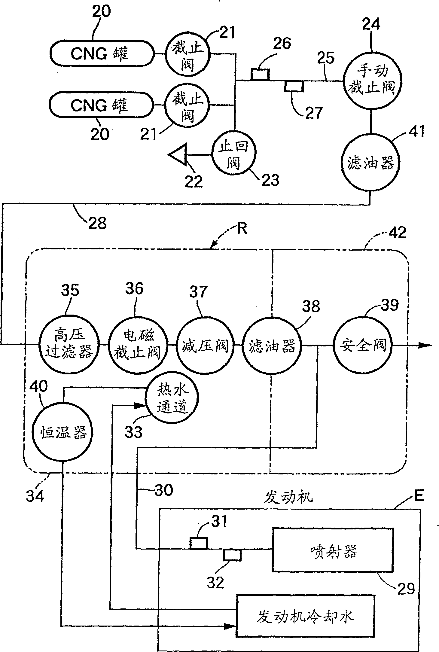
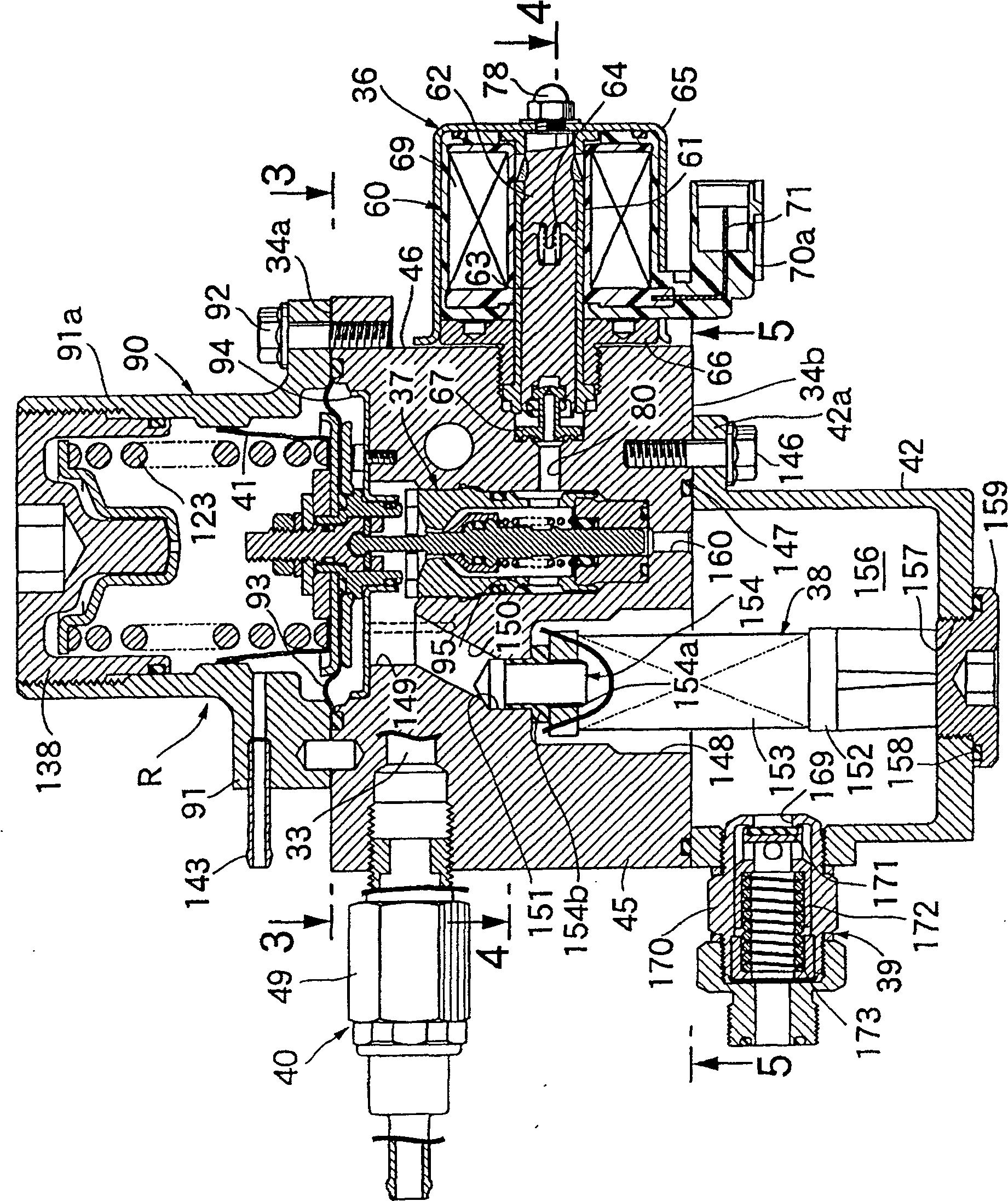
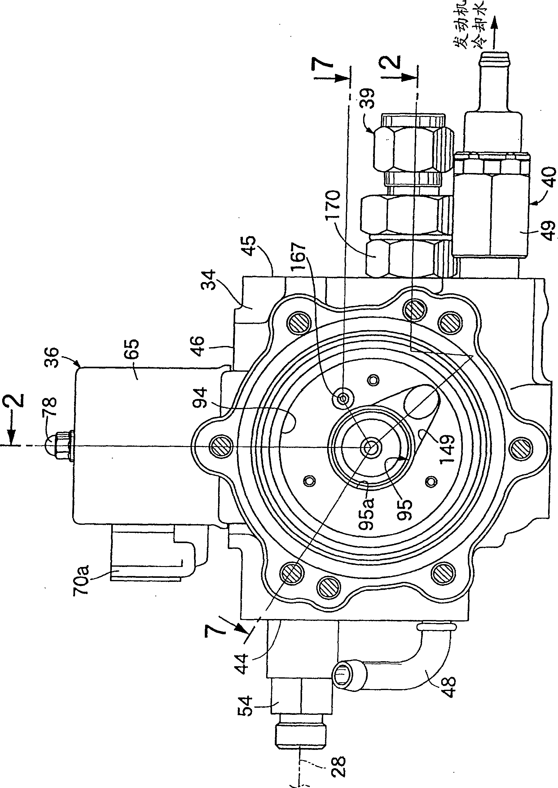
[0048] Figure 1 to Figure 11 shows an embodiment of the present invention.

[0049] first in figure 1 Among them, compressed natural gas (Compressed Natural Gas: hereinafter referred to as CNG) as a fuel gas is stored in one or more CNG tanks 20 at a high pressure of, for example, 25 to 1 MPa. These CNG tanks 20 respectively have container shutoff valves 21, They are commonly connected to the filling port 22 via a check valve 23 and to a manual shutoff valve 24 , and a pressure sensor 26 and a temperature sensor 27 are additionally provided in a pipe 25 between each container shutoff valve 21 and the manual shutoff valve 24 .

[0050] When the container shut-off valve 21 and the manual shut-off valve 24 are opened, the CNG from the above-mentioned CNG tank 20 is guided to the gas regulator R through the high-pressure pipeline 28 having an oil filter 41 for removing The oil that may be mixed when the compressor fills the CNG tank 20 with CNG is depressurized by the regulator...


PUM


Abstract

PROBLEM TO BE SOLVED: To simplify a gas depressurizing system, and to reduce cost, in a regulator for gas wherein at least an electromagnetic shut-off valve and a pressure reducing valve interposed between an inlet passage and an outlet passage are provided on a body provided with the inlet passage and the outlet passage. SOLUTION: In the regulator for the gas wherein at least the electromagnetic shut-off valve 36 and the pressure reducing valve 37 interposed between the inlet passage 59 and the outlet passage 164 are provided on the body 34 provided with the inlet passage 59 and the outlet passage 164, an oil filter 38 interposed between the pressure reducing valve 37 and the outlet passage 164 is mounted on the body 34. Since the oil filter is assembled into the body, the gas depressurizing system can be simplified and the cost can be reduced by integrating at least the electromagnetic shut-off valve, the pressure reducing valve and the oil filter into the body.

Description

technical field [0001] The present invention relates to a pressure reducing valve and a regulator for gas, in particular to such a pressure reducing valve and a regulator for gas including the pressure reducing valve. The pressure reducing valve includes: a valve housing, which is combined by a body and a cover The diaphragm is clamped between the body and the cover at its peripheral edge; the diaphragm rod is held at the center of the diaphragm by a diaphragm holder; the valve shaft is detachably connected to the diaphragm rod at one end thereof, And the other end thereof is slidably fitted in a guide hole, which is provided on the body side; and a valve body, which is provided at the middle part of the above-mentioned valve shaft, can be seated on the valve seat, and the above-mentioned valve seat is fixed It is arranged in the above-mentioned body, and a valve hole is opened in the central part, and the valve shaft is movably inserted through the valve hole. Background te...

Claims


Application Information

Patent Timeline
Patent Type & Authority Patents(China)
IPC IPC(8): G05D16/06F01M11/03F02M21/02
CPCY02T10/32Y02T10/30
Inventor 石川和记
Owner KEIHIN CORP
Learn More