Supercharge Your Innovation With Domain-Expert AI Agents!

Heat exchange plate for plate heat exchanger

A technology of plate heat exchanger and heat exchange plate, applied in the direction of heat exchanger types, indirect heat exchangers, heat exchange equipment, etc., can solve the problems of many molds, difficult assembly and operation, etc., to improve heat transfer coefficient and reduce equipment Investment, the effect of improving positioning accuracy

Active Publication Date: 2009-07-15
SHANDONG BEICHEN MECHANICAL & ELECTRICAL EQUIP
View PDF7 Cites 0 Cited by
  • Summary
  • Abstract
  • Description
  • Claims
  • Application Information

AI Technical Summary

Problems solved by technology

[0002] The plate heat exchanger is a high-efficiency heat exchange equipment with a metal corrugated plate as the heat transfer element. The corrugations in the heat exchange plate adopt a symmetrical design, that is, the angles of the corrugations on both sides of the center line of the same plate are the same, so although the manufacturing process is simple , but in the usual heat exchange state, the flow rate of the hot medium and the cold medium are different, and two kinds of plates with different angles are used to cross each other for assembly. Many molds are needed in the manufacture, and it is not easy to operate in the assembly.

Method used


Image

  • Heat exchange plate for plate heat exchanger
  • Heat exchange plate for plate heat exchanger
  • Heat exchange plate for plate heat exchanger

Examples


Embodiment 1

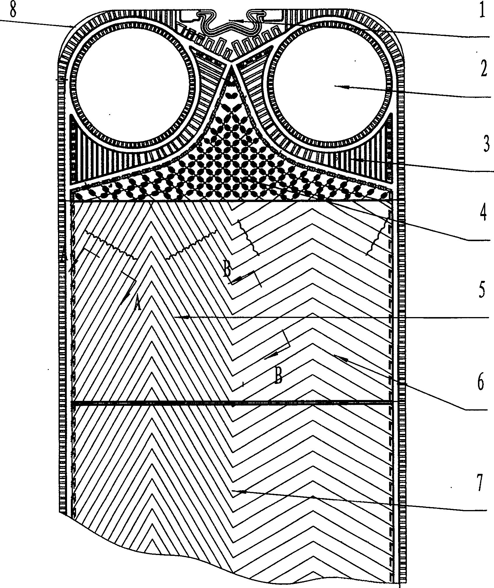
[0014] Embodiment 1, a heat exchange plate of a plate heat exchanger, made of pressed stainless steel plate, including positioning hole 1, medium inlet and outlet 2, inlet and outlet diversion area 3, diversion area 4, heat transfer area, its structure is: The plate corrugation in the heat transfer zone is divided into two sides by the center line of the plate, and the obtuse-angle corrugation 6 on one side is connected to the acute-angle corrugation 5 on the other side.

Embodiment 2

[0015] Embodiment 2, a heat exchange plate of a plate heat exchanger, made of pressed stainless steel plate, including positioning hole 1, medium inlet and outlet 2, inlet and outlet diversion area 3, diversion area 4, heat transfer area, its structure is: The plate corrugation in the heat transfer zone is divided into two sides by the center line of the plate, one side is a 120° obtuse angle corrugation 6 connected to the other side 60° acute angle corrugation 5, and a reinforcing rib 7 is added between the two corrugations.

Embodiment 3

[0016] Embodiment 3, a heat exchange plate of a plate heat exchanger, made of pressed stainless steel plate, including positioning hole 1, medium inlet and outlet 2, inlet and outlet diversion area 3, diversion area 4, and heat transfer area, its structure is: The plate corrugation in the heat transfer zone is divided into two sides by the center line of the plate, one side is a 120 ° obtuse angle corrugation 6 connected to the other side of the 60 ° acute angle corrugation 5, and a reinforcing rib 7 is added between the two corrugations; The diameter ratio of the corrugated runners on both sides of the heat plate is 1:2.2; the four corners of the heat exchange plate are provided with corner lock pieces 8.


PUM


Abstract

The invention discloses a heat exchange plate of a plate heat exchanger, which belongs to a part of heat exchange equipment in which the heat exchange medium does not directly contact, especially a heat exchange equipment for fixed plates or lamination channels of two exchange media, each medium and A part of a heat exchange device in which different sides of a channel are in contact. The heat exchange plate includes a positioning hole, a medium inlet and outlet, an inlet and outlet diversion area, a diversion area, and a heat transfer area, and is characterized in that: the plate corrugation in the heat transfer area is divided into two sides by the center line of the plate, Obtuse corrugations on one side are connected to acute corrugations on the other side. The beneficial effect of the present invention is that since the corrugation of the plate adopts corrugations of different angles on the center line of the plate, it is better to achieve the matching between the heat exchange flow rate and the allowable pressure drop, and at the same time, the diameter ratio of the corrugated flow channels on both sides of the heat exchange plate is different. , can make the flow rate of cold and hot medium between the plates close to or equal, and increase the heat transfer coefficient by 5-10%. The invention is suitable for upgrading products of original production enterprises.

Description

technical field [0001] The invention belongs to parts of heat exchange devices in which the heat exchange media are not in direct contact, in particular to fixed plates or laminated channels for two exchange media, parts of heat exchange devices in which the media are in contact with different sides of the channels . Background technique [0002] The plate heat exchanger is a high-efficiency heat exchange equipment with a metal corrugated plate as the heat transfer element. The corrugations in the heat exchange plate adopt a symmetrical design, that is, the angles of the corrugations on both sides of the center line of the same plate are the same, so although the manufacturing process is simple , but in the usual heat exchange state, the flow rate of the hot medium and the cold medium are different, and two kinds of plates with different angles are used to cross each other for assembly. Many molds are needed in the manufacture, and it is not easy to operate in the assembly. ...

Claims


Application Information

Patent Timeline
Patent Type & Authority Patents(China)
IPC IPC(8): F28F3/04F28D9/00
Inventor 唐金山
Owner SHANDONG BEICHEN MECHANICAL & ELECTRICAL EQUIP
Features
  • R&D
  • Intellectual Property
  • Life Sciences
  • Materials
  • Tech Scout
  • Unparalleled Data Quality
  • Higher Quality Content
  • 60% Fewer Hallucinations
Learn More