
Drilling tool with alternating cutting plates therefor

A technology for drilling tools and blades, applied in drilling tool accessories, cutting blades, manufacturing tools, etc., can solve problems such as insufficient removal of replaceable blade breakage, and achieve the effect of reducing chip jamming

Inactive Publication Date: 2009-07-22
KOMET GROUP GMBH
View PDF7 Cites 3 Cited by
  • Summary
  • Abstract
  • Description
  • Claims
  • Application Information

AI Technical Summary

Problems solved by technology

However, it has been found in the use of such drilling tools that a protective bevel formed in this way is not sufficient to exclude the risk of breaking the replaceable insert at this point.

Method used


Image

  • Drilling tool with alternating cutting plates therefor
  • Drilling tool with alternating cutting plates therefor
  • Drilling tool with alternating cutting plates therefor

Examples


Embodiment Construction

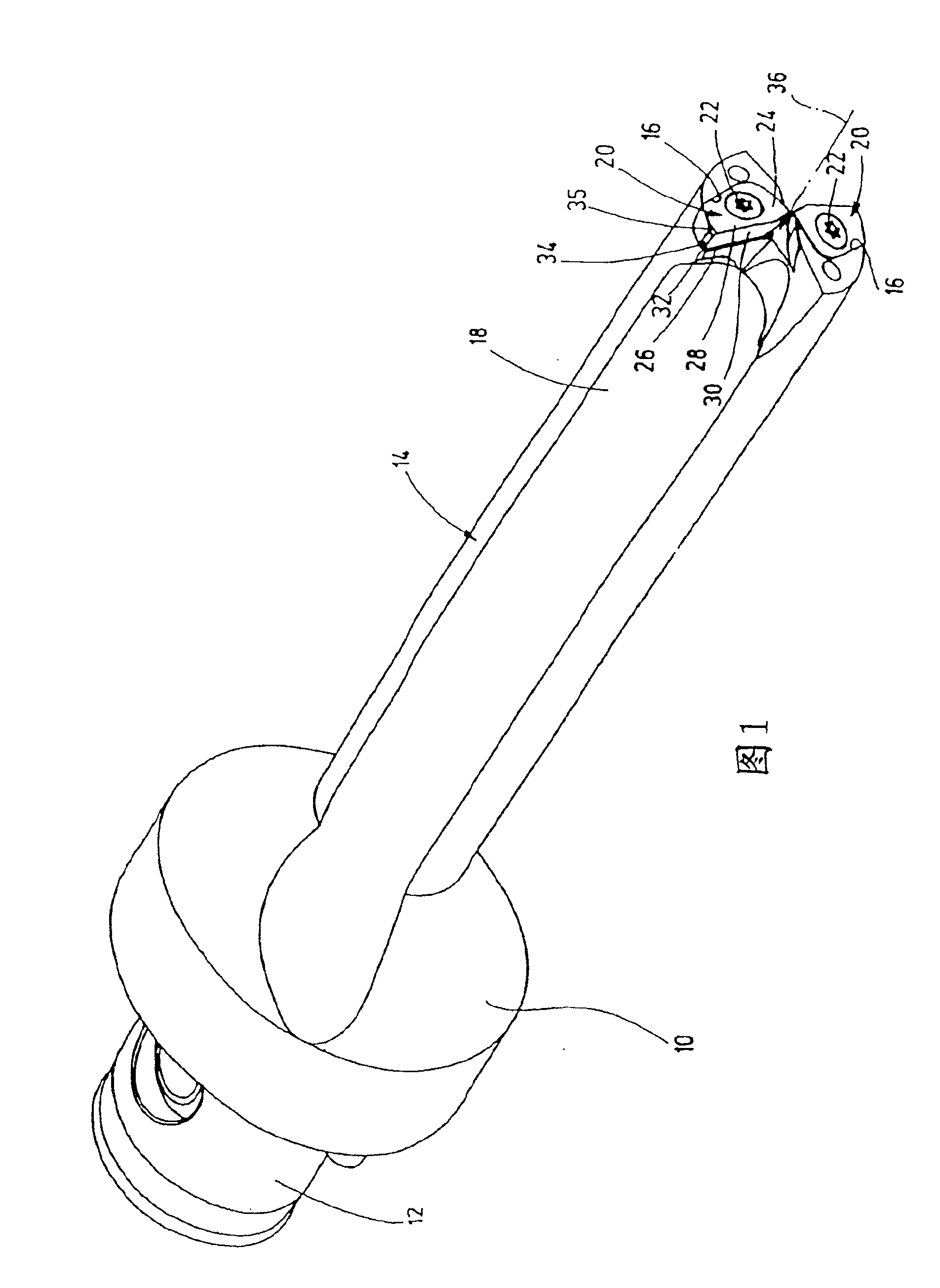
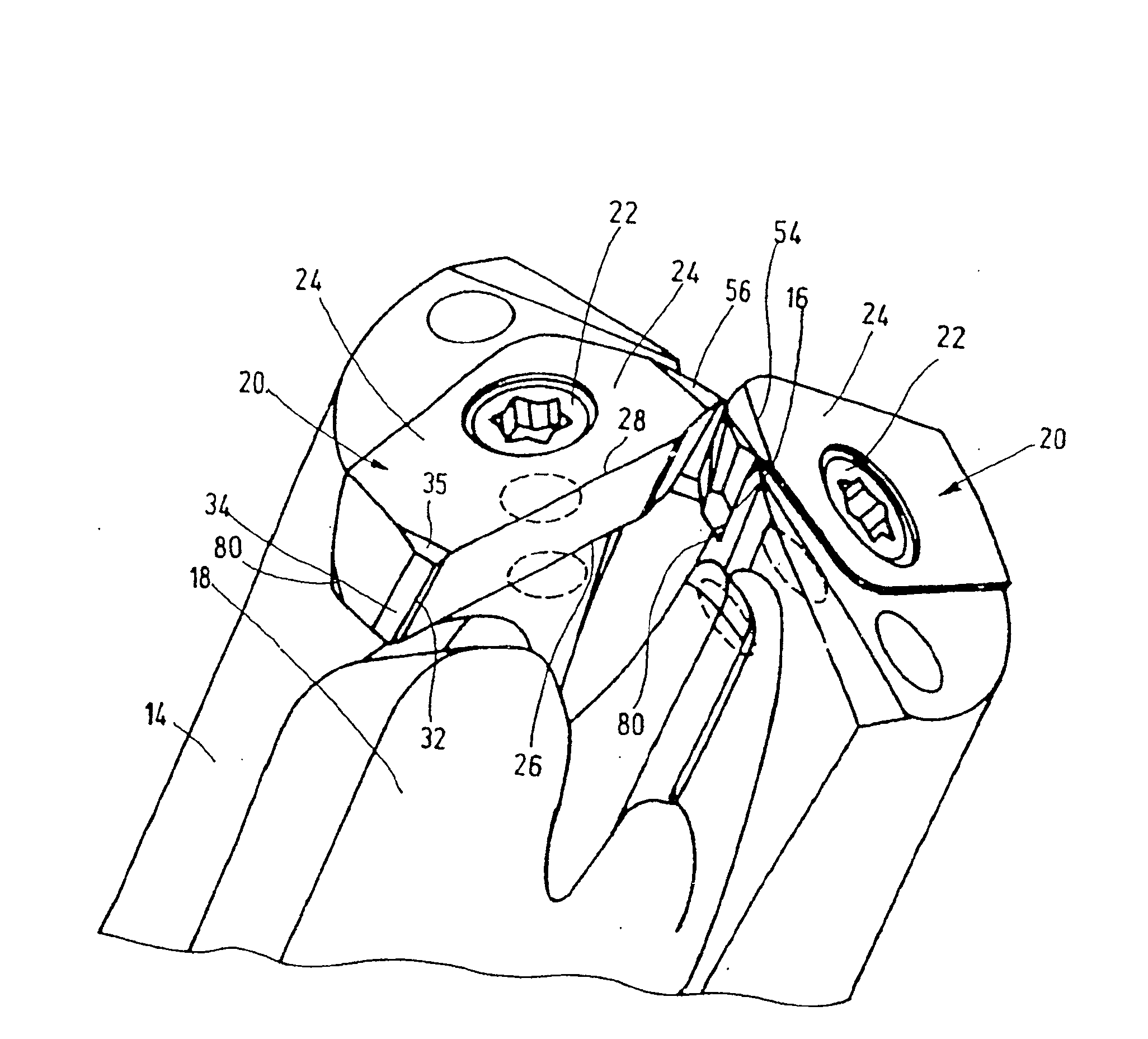
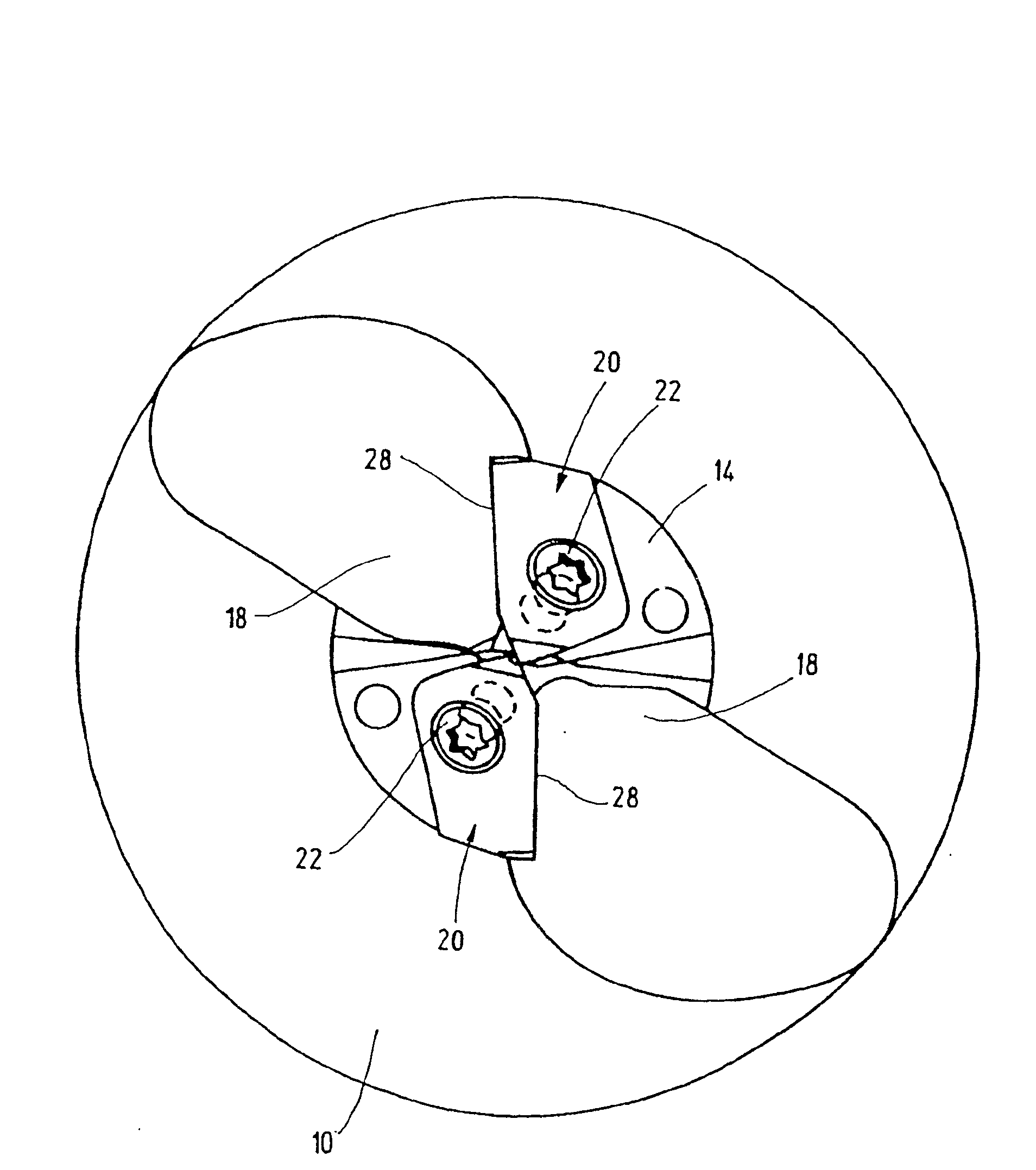
[0034] The drilling tool shown in the drawings consists of a double-edged solid drill. These drilling tools are suitable for machine tools and for this purpose have a coupling shank 12 for connection to a not shown machine tool spindle, which is defined by a coupling flange 10 for flat positioning. Furthermore, a longitudinally extending base body 14 is connected via a connecting flange 10 , which is provided on the end face with two insert seats 16 , from which chip flutes 18 extend along the length of the base body 14 . Two replaceable blades 20 of the same structure are arranged in the blade seat 16 and fixed on the base body 14 by fixing bolts 22 .

[0035] The insert 20 arranged upright according to FIGS. 1 to 5 has a cutting face 24 and a bearing face 26 facing away from this cutting face, which are aligned plane-parallel to one another. On the chip flute side, the cutting face 24 is bounded by a main edge 28 and a chip surface 30 adjoining the main edge and opening int...


PUM


Abstract

The device is fitted with two exchangeable cutting plates (20), each provided with a wedge-shaped cutting edge formed by their upper (24) and front surfaces (28). The inclined main cutting edges (28) are combined to form a transversal cutting area interrupted by a central gap. The upper surfaces (28) are positively inclined in relation to the direction of motion, while the central inclinations (56) are negative.

Description

technical field [0001] The invention relates to a drilling tool with a base body rotatable about a drill axis, with two insert seats arranged in the top of the base body, and with a centrally located insert corner that is replaceably inserted into the insert seats Replaceable inserts facing each other across the drill axis with a central clearance, these exchangeable inserts have a main edge from a radially outer leading edge to the corner of the central insert and each a Chip faces and cutting faces that meet at the main edges and form a cutting wedge, wherein the main edges of the exchangeable inserts together form a chisel edge interrupted by a central recess on a central, in particular chamfered, edge section. Furthermore, the invention relates to a replaceable insert for a drilling tool of the type described above. Background technique [0002] Drilling tools of this type are used as double-edged solid drills, which are constructed similarly to a twist drill but with r...

Claims


Application Information

Patent Timeline
Patent Type & Authority Patents(China)
IPC IPC(8): B23B51/04B23B27/14B23B51/00
CPCB23B2200/085B23B2200/125B23B51/048B23B2200/204Y10S408/713Y10T408/9097B23B2200/323B23B27/141B23B2200/0423Y10T408/45B23B51/00B23B51/02B23B51/04
Inventor J·克鲁申斯基H·莫洛克H·许特P·洛伊策
Owner KOMET GROUP GMBH
Learn More