Eureka AIR delivers breakthrough ideas for toughest innovation challenges, trusted by R&D personnel around the world.

W flame boiler primary air waste-steam replacement method and apparatus for

A secondary air and boiler technology, applied in the combustion method, non-flammable liquid/gas transportation, lighting and heating equipment, etc., can solve the problems of insufficient air jet stroke, reduced main air flow rate, and reduced airflow rigidity, etc. Ash carbon content, enhanced replenishment and mixing, and effects of improving burnout

Inactive Publication Date: 2009-07-22
BEIJING JIAOTONG UNIV
View PDF6 Cites 0 Cited by
  • Summary
  • Abstract
  • Description
  • Claims
  • Application Information

AI Technical Summary

Problems solved by technology

[0011] 2. The separation effect of the pulverized coal cyclone separator is not ideal
Due to the unsatisfactory separation effect of the pulverized coal cyclone separator, the fine pulverized coal particles cannot be separated and enter the furnace with the exhaust gas; the fineness and concentration of the pulverized coal particles are important factors for the ignition of the pulverized coal airflow, and the The average fineness of pulverized coal particles in the main airflow becomes coarser and the concentration decreases, which worsens the ignition and stable combustion conditions of the main airflow
[0012] 3. One air jet is not enough
The lack of gas wind increases, the velocity of the main air flow of the primary air decreases, the rigidity of the air flow decreases, and the penetration depth and stroke of the main air flow are not long enough, resulting in insufficient amount of the main air flow to absorb the radiant heat of the furnace and to entrain the high-temperature hot flue gas, resulting in coal dust Poor Airflow Ignition Performance

Method used


Image

  • W flame boiler primary air waste-steam replacement method and apparatus for
  • W flame boiler primary air waste-steam replacement method and apparatus for
  • W flame boiler primary air waste-steam replacement method and apparatus for

Examples


Embodiment Construction

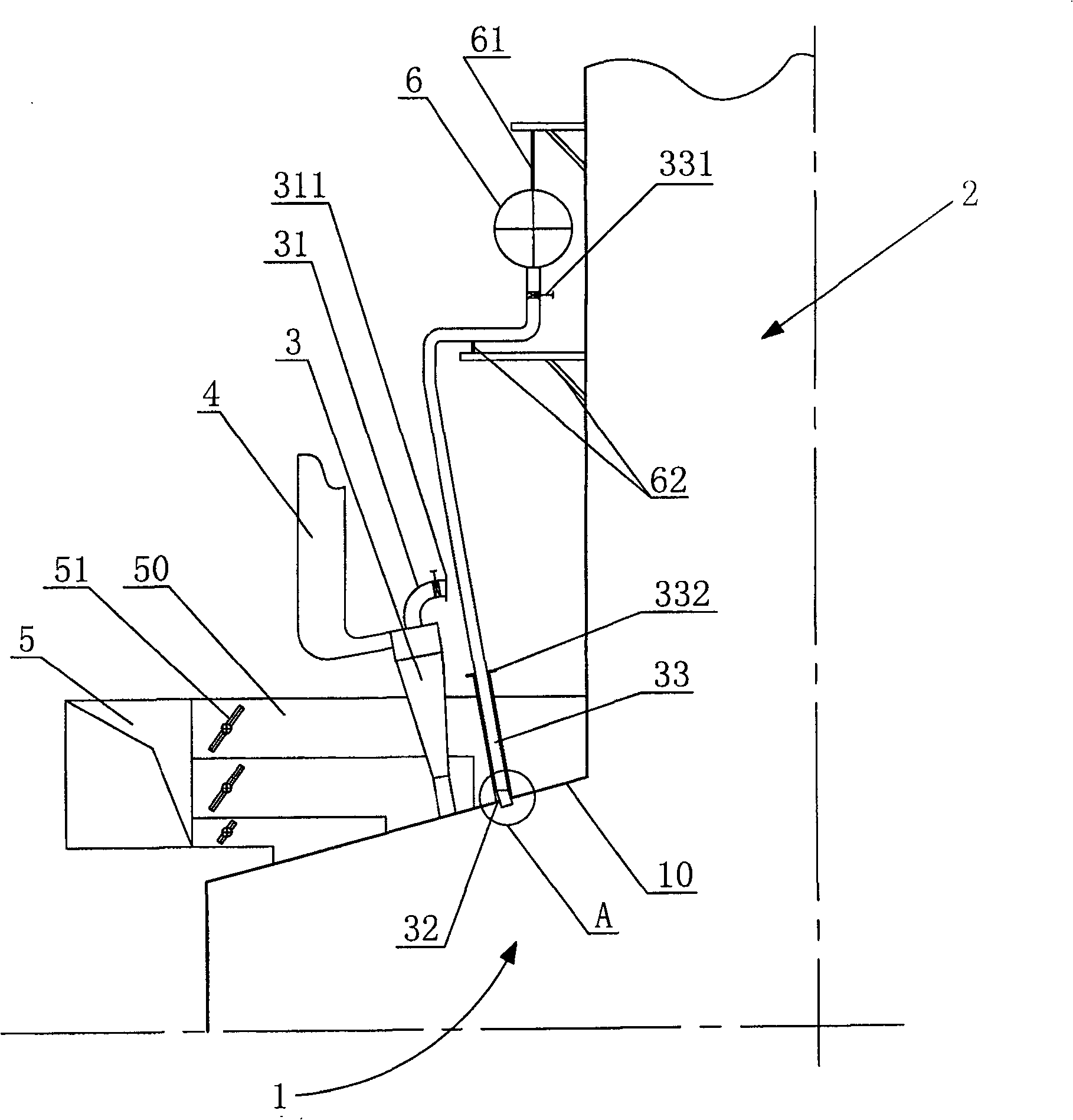
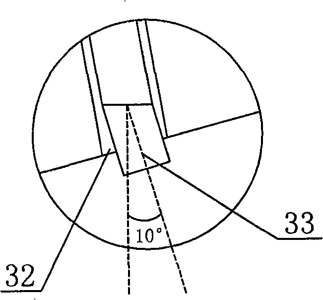
[0035] see figure 2 , 3 as shown,

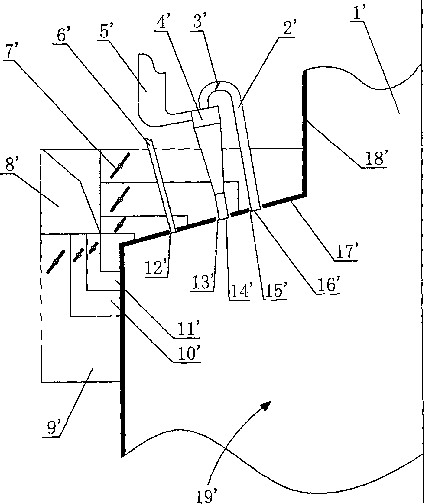
[0036]A method for replacing the primary air exhaust air of a W flame boiler according to the present invention: disconnect the primary air exhaust air pipe 31 of the cyclone separation type pulverized coal thick-lean burner 3 on the front and rear furnace arches 10 of the existing W flame boiler, and cancel the access to the combustion chamber. The exhaust air duct of the room; using the original primary air exhaust nozzle 32 and the position, 5% to 30% of the total amount of secondary air is transferred from this position at an angle of 0° to 60° to the vertical direction and The speed of 10-50m / s is injected downward into the combustion chamber.

[0037] The present invention is a W-flame boiler primary air depleted gas replacement device, which includes a combustion chamber 1 at the lower part of the boiler body, a burnout chamber 2 at the upper part of the boiler body, and a cyclone separation type pulverized coal thick-lean burner 3...


PUM


Abstract

A method for replacing the primary air exhaust air of a W flame boiler, which disconnects the primary air exhaust air pipes of the pulverized coal burners on the front and rear arches of the existing W flame boiler, and cancels the exhaust air pipes leading to the combustion chamber; For some nozzles and locations where the primary air is exhausted, 5% to 30% of the total secondary air is injected downward into the combustion chamber at an angle of 0° to 60° from the vertical and at a speed of 10 to 50m / s. . A primary air exhaust gas replacement device for a W flame boiler is inserted into a secondary air duct at the original primary air exhaust gas nozzle of a pulverized coal burner. Compared with the prior art, the present invention has the following advantages: 1) It can eliminate the irrationality of the existing W flame boiler air supply mode; 2) It can improve the stability of the pulverized coal air flow flame, increase the flame stroke, and strengthen the oxygen amount in the later stage of combustion 3) Make full use of the original combustion system structure, which is very suitable for the technical transformation of the existing W flame boiler.

Description

technical field [0001] The invention relates to a method and a device for replacing primary air exhaust gas of a W-flame boiler, belonging to the technical field of W-flame boiler combustion. Background technique [0002] my country is one of the few countries in the world rich in anthracite reserves, with proven reserves of nearly 120 billion tons. However, due to the low volatile matter content of anthracite and the high precipitation temperature of volatile matter, it is difficult to ignite the pulverized coal airflow, the combustion is unstable, and it is not easy to burn out, resulting in increased mechanical incomplete combustion during boiler operation and low boiler efficiency. In order to improve the operation safety and economy of boilers burning anthracite and other low-response coals, my country introduced the FW-W flame boiler combustion technology of the American FW Company in the late 1980s. At the same time, the domestic Dongfang Boiler Factory has introduce...

Claims


Application Information

Patent Timeline
Patent Type & Authority Patents(China)
IPC IPC(8): F23L9/00
Inventor 周岩梅蒋宏利蒋淑艳
Owner BEIJING JIAOTONG UNIV
Why Eureka
Eureka Blog
Learn More