Gradual-change cavity microperforated broad band sound absorption type sound barrier
What is Al technical title?
Al technical title is built by PatSnap Al team. It summarizes the technical point description of the patent document.
A micro-perforation and sound barrier technology, applied in the field of acoustics, can solve the problems of narrow sound absorption frequency band, high temperature resistance, poor weather resistance, etc., and achieve the effect of sound absorption frequency band, good noise reduction effect, and superior weather resistance
Active Publication Date: 2009-08-05
SHAZC GRP CORP LTD
View PDF8 Cites 2 Cited by
Summary
Abstract
Description
Claims
Application Information
AI Technical Summary
This helps you quickly interpret patents by identifying the three key elements:
Problems solved by technology
Method used
Benefits of technology
Problems solved by technology
The double-layer micro-perforation device can solve the problems of weather resistance and secondary pollution of traditional fiber materials, but the processing is more complicated and the cost is high when used on the sound barrier
Foam glass has the disadvantage of being fragile, the sound absorption coefficient is 0.4-0.6, and the sound absorption frequency band is narrow
Polyurethane sound-absorbing foam has disadvantages such as high temperature resistance and poor weather resistance
Method used
Image
Click on the blue label to locate the original text in one second.
Reading with bidirectional positioning of images and text.
Examples
Embodiment 1
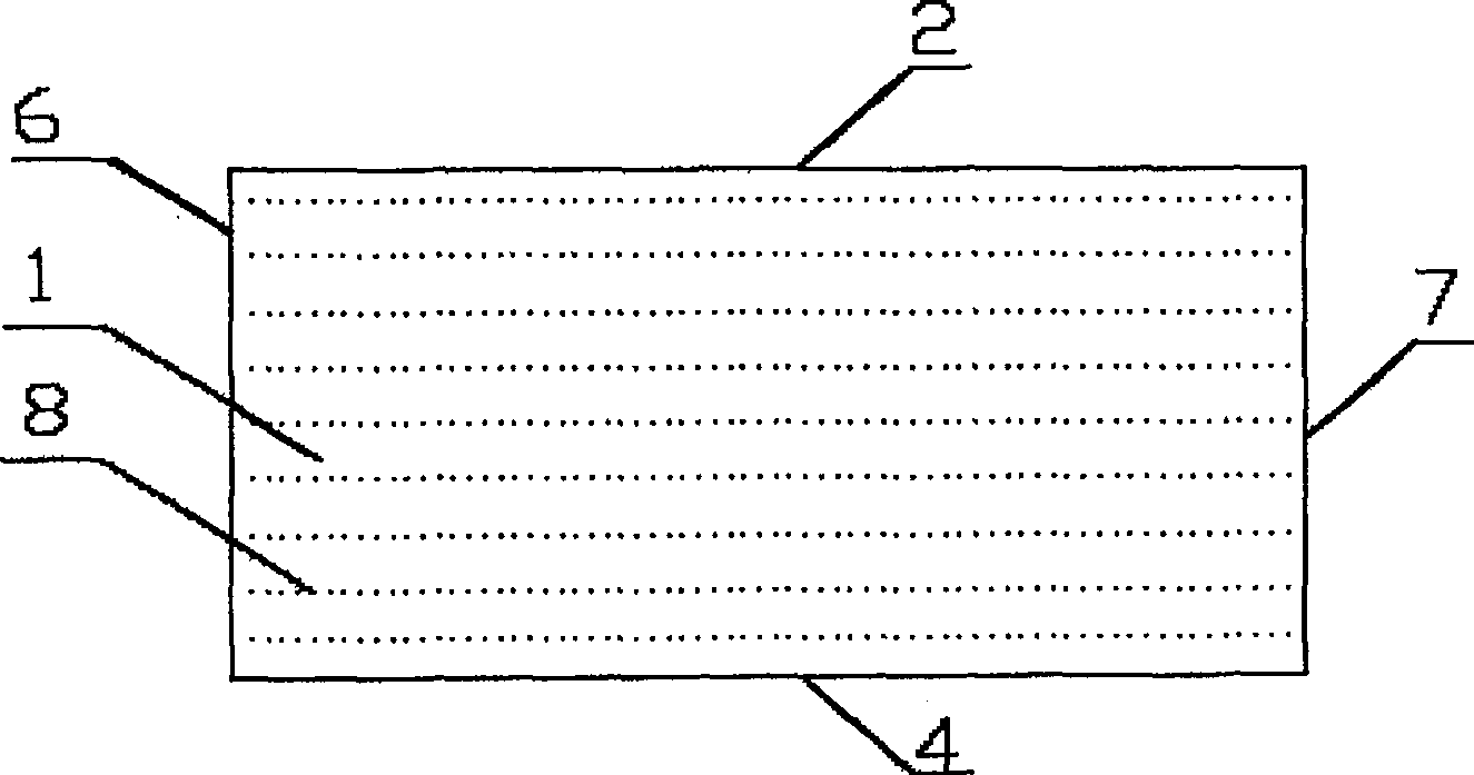
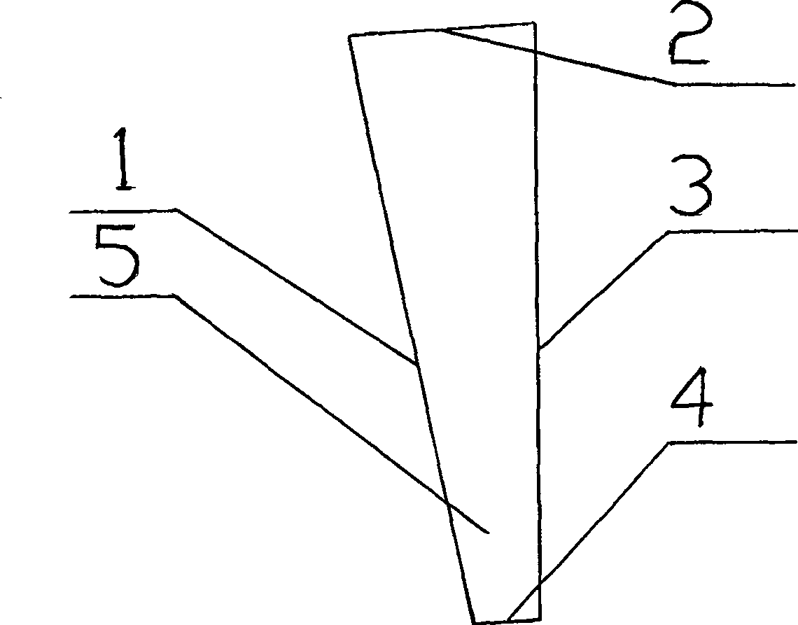
[0021] Embodiment 1: the following parts are pressed Figure 1-Figure 2 Those skilled in the art can successfully implement the connection in the manner shown. The micro-perforated panel 1 , the upper end surface 2 , the back plate 3 , the lower end surface 4 , the left end surface 6 , and the right end surface 7 are connected to form a closed cavity 5 . The micro-perforated panel 1 is made of 1mm thick alumina plate. The size of the micro-perforated panel 1 is 1.0m in length and 0.503m in width. 0.8mm. The back plate 3 is made of 1.2mm thick steel plate, the upper end face 2, the lower end face 4, the left end face 6, and the right end face 7 are made of 1 mm thick aluminum plate. ~15cm linear gradient. The angle between the upper end surface 2 and the water line is 4°, the angle between the lower end surface 4 and the horizontal line is 4°, and the angle between the micro-perforated panel 1 and the vertical line is 11°.
PUM
Abstract
The invention belongs to the technical field of acoustics, and in particular relates to a non-fiber novel gradually changing cavity micro-perforated sound-absorbing sound barrier body. It is composed of micro-perforated panel, upper end surface, lower end surface, left end surface, right end surface and back plate. The micro-perforated panel, upper end surface, lower end surface, left end surface, right end surface and back plate are connected to form a closed cavity, and the depth of the cavity is linear Gradient, the maximum depth is 2.5-3.5 times the minimum depth. The microperforated panel is distributed with micropores occupying an area of 0.5% to 3% of the panel area, and the diameter of the micropores is 0.6 to 1.2mm. When in use, it only needs to install the present invention in the column of the sound barrier or other places requiring sound absorption treatment. The invention has the advantages of simple device, easy processing, thin shape and light weight, excellent sound absorption performance, the sound absorption frequency band width of which the sound absorption coefficient is greater than 0.4 exceeds 2 octaves, wide application, easy cleaning, high temperature resistance, and excellent weather resistance , can be completely recycled, completely avoiding the problem of secondary pollution, and has excellent environmental protection functions.
Description
technical field [0001] The invention belongs to the technical field of acoustics, and specifically relates to a gradually changing cavity micro-perforated broadband sound-absorbing sound barrier body used on both sides of a traffic arterial road and in an environment with serious noise pollution. Background technique [0002] While the increase of economic activities improves people's living standards, it also makes the problem of noise pollution more and more serious. Complaints caused by the impact of noise pollution on people account for more than 50% of all kinds of environmental complaints in economically developed cities, especially traffic noise. Complaints rank first among noise complaints. [0003] Noise barrier is one of the important measures in traffic noise control technology. At present, the sound-absorbing sound barriers commonly used at home and abroad are mostly porous fiber materials such as glass wool, rock wool, etc., plus perforated protective panels. ...
Claims
Application Information
Patent Timeline
Application Date:The date an application was filed.
Publication Date:The date a patent or application was officially published.
First Publication Date:The earliest publication date of a patent with the same application number.
Issue Date:Publication date of the patent grant document.
PCT Entry Date:The Entry date of PCT National Phase.
Estimated Expiry Date:The statutory expiry date of a patent right according to the Patent Law, and it is the longest term of protection that the patent right can achieve without the termination of the patent right due to other reasons(Term extension factor has been taken into account ).
Invalid Date:Actual expiry date is based on effective date or publication date of legal transaction data of invalid patent.