Electrothernal tube and its forming method

A molding method and electric heating tube technology, applied in the direction of the shape of the heating element, can solve the problems of affecting assembly, expansion and contraction damage, and difficulty in controlling the shape and size of the electrical connection end.

Inactive Publication Date: 2009-08-05
何伟
View PDF7 Cites 0 Cited by
  • Summary
  • Abstract
  • Description
  • Claims
  • Application Information

AI Technical Summary

Problems solved by technology

The disadvantage is that when the metal tube is stamped and formed by the stamping die, it will extend to both ends due to the smooth surface of the metal tube. On the one hand, it makes it difficult to control the dimensions of the two electrical connection ends of the electric heating tube, which affects the assembly.
On the other hand, the insulating powder inside the metal tube cannot be compacted, and it is easy to accumulate air in the space. When the electric heating tube is used, it will expand with heat and contract with cold. Expansion and contraction leading to damage

Method used


Image

  • Electrothernal tube and its forming method
  • Electrothernal tube and its forming method

Examples


Embodiment Construction

[0016] Below in conjunction with the accompanying drawings, the specific implementation of the forming method of the electric heating tube of the present invention is further described in detail:

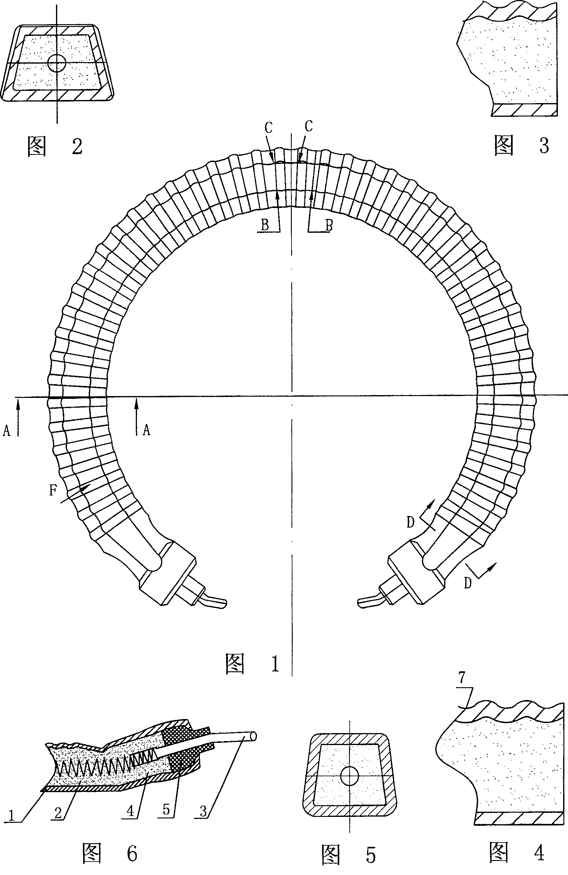
[0017] The electric heating tube of the present invention includes a metal tube 1 , insulating powder 2 , resistance wire 4 , insulating piece 5 and metal rod 3 . The metal tube 1 is an aluminum tube, the insulating powder 2 is magnesium oxide powder, the insulating part 5 is a porcelain post, and the metal rod 3 is a steel lead post.

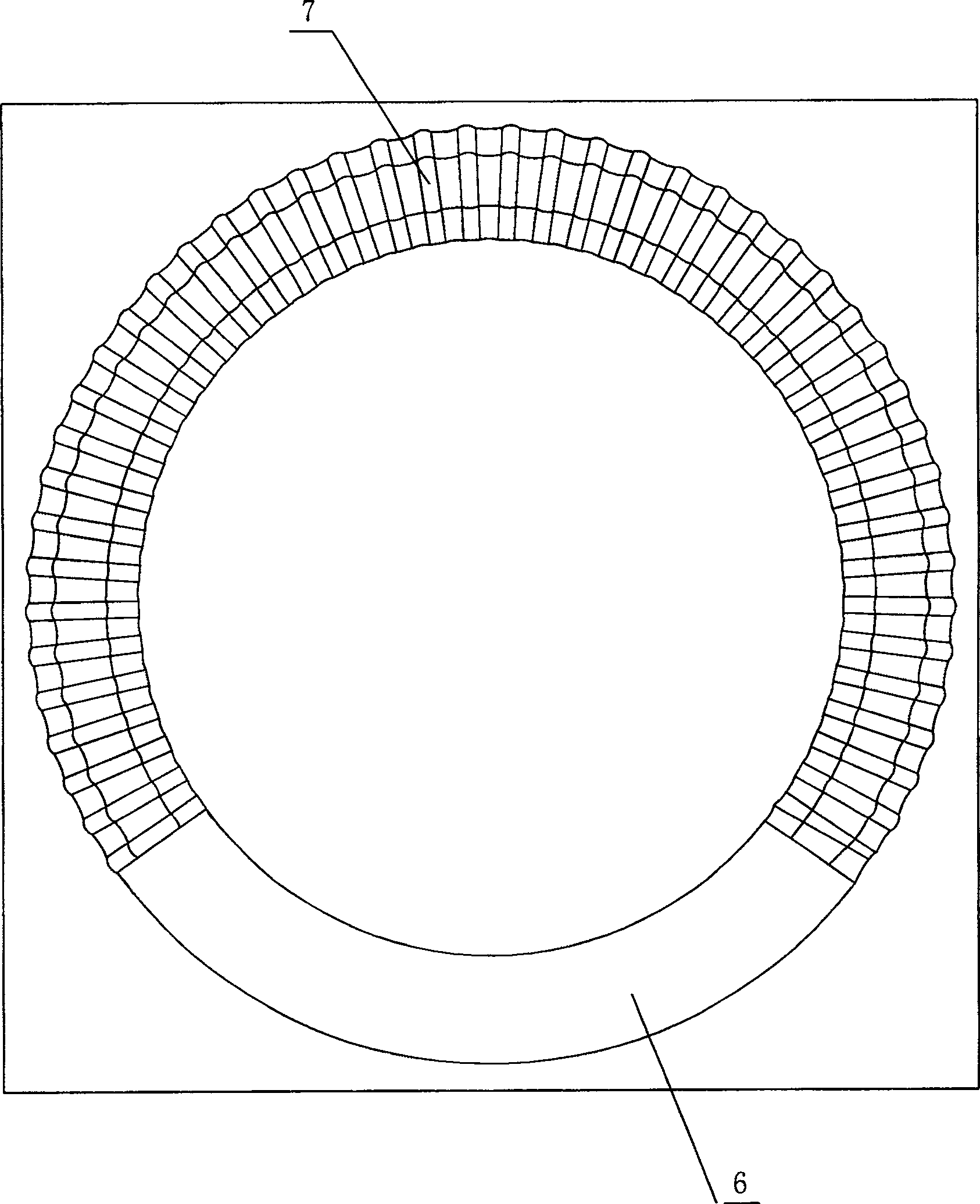
[0018] As shown in Figures 1-6, the electric heating tube is bent into a C-shape from a circular metal tube 1 with a cross-section, and then stamped to have a concave-convex structure on the surface and at least one surface is a planar structure. The advantage is that the circular metal tube 1 is easy to bend, and the distance between the internal resistance wire 4 and the tube wall of the metal tube 1 is uniform. The metal rod 3 is arranged in the ...


PUM


Abstract

The invention belongs to the technical field of electric heaters, and relates to an electric heating tube and a forming method thereof. The invention solves the problem that the existing electric heating tube, when the metal tube is stamped and formed by the stamping die, the metal tube will extend to both ends, resulting in the difficulty of controlling the external dimension and the problem that the insulating powder inside cannot be compacted. The electric heating tube includes insulating powder and resistance wire arranged in the metal pipe, an insulator blocked in the nozzle of the metal pipe and a metal rod arranged in the insulator to keep isolation from the metal pipe and connected to the resistance wire. The metal pipe described above is punched and formed from a metal pipe with a circular cross-section, and its surface has a concave-convex structure and at least one surface is a plane structure. The forming method of the electric heating tube is to place the electric heating tube in the cavity of the A stamping die that is compatible with it, and distribute the raised parts on the surface of the concave cavity, and press the B stamping die and the A stamping die together to make it The surface of the metal tube is concave-convex, and the wall is extended and formed, and the electric heating tube is taken out from the stamping die.

Description

technical field [0001] The invention belongs to the technical field of electric heaters, and relates to an electric heating tube and a forming method thereof. Background technique [0002] The structure of the existing electric heating tube used for the bottom of the kettle body of an electric kettle includes a metal tube, a resistance wire arranged in the metal tube, and insulating powder, such as magnesium oxide powder, between the resistance wire and the metal tube. When it is manufactured, the resistance wire is first placed at the axis of the metal tube, and an insulating member, such as a porcelain column, is placed at one port of the metal tube so that the end of the resistance wire passes through it, and the ceramic column is blocked in the metal tube. Insulating powder is poured into the port from the other end of the metal tube, and the metal tube is vibrated so that the insulating powder can tightly wrap the resistance wire and separate it from the metal tube. Al...

Claims


Application Information

Patent Timeline
Patent Type & Authority Patents(China)
IPC IPC(8): H05B3/52
Inventor 何伟
Owner 何伟
Why Eureka
Try Eureka