
Multiple compressor

A compressor and multiple technologies, applied in the field of compressors, can solve the problems of compressor volume becoming larger and larger, and achieve the effect of minimum operating noise and elimination of unbalanced racks

Inactive Publication Date: 2009-08-26
LG ELECTRONICS (TIANJIN) APPLIANCES CO LTD
View PDF5 Cites 0 Cited by
  • Summary
  • Abstract
  • Description
  • Claims
  • Application Information

AI Technical Summary

Problems solved by technology

However, if the design is changed in this way, the other components of the compressor will also become larger accordingly, so there will be a disadvantage that the entire volume of the compressor will become larger.

Method used


Image

  • Multiple compressor
  • Multiple compressor
  • Multiple compressor

Examples


Embodiment Construction

[0050] The multiple compressor embodiment of the present invention will be described in detail below with reference to the accompanying drawings.

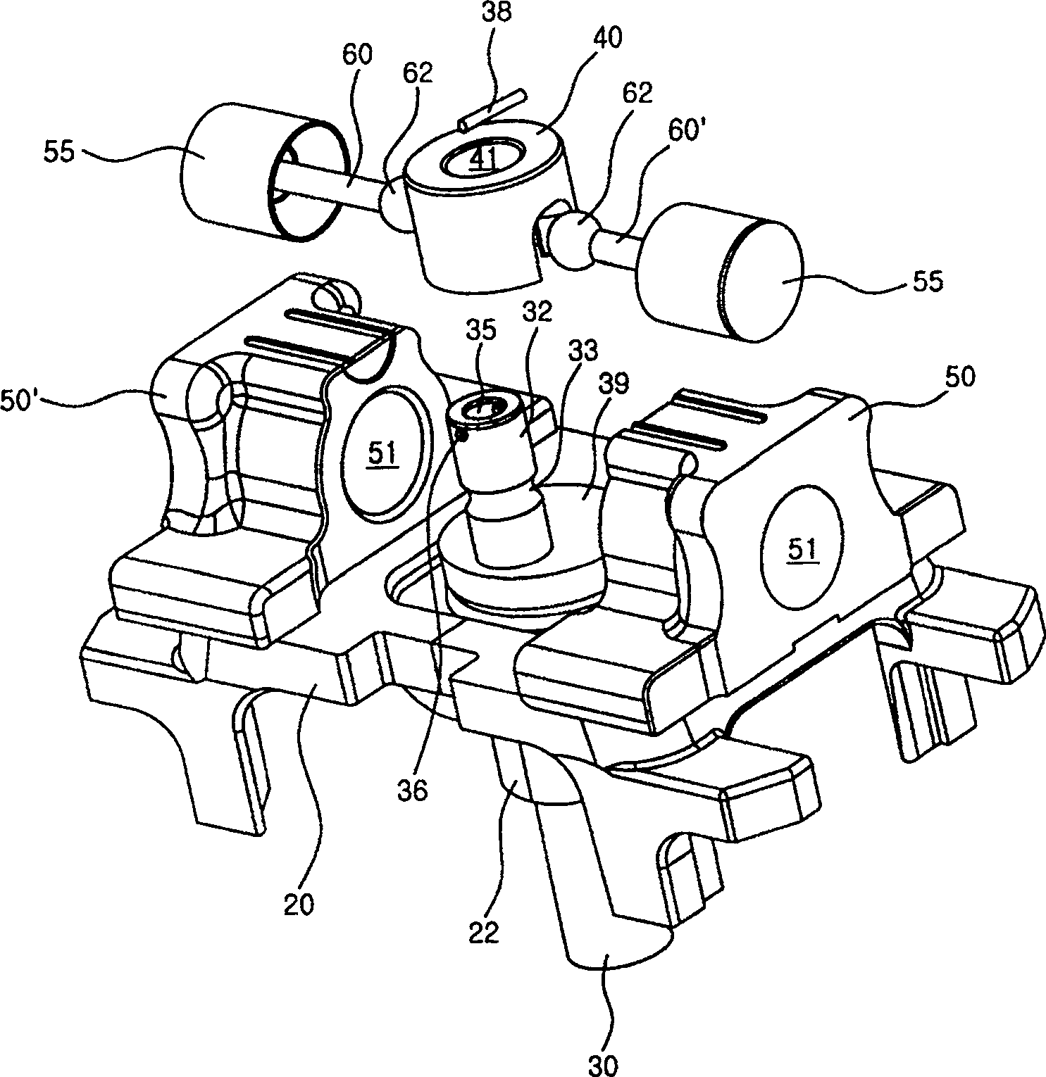
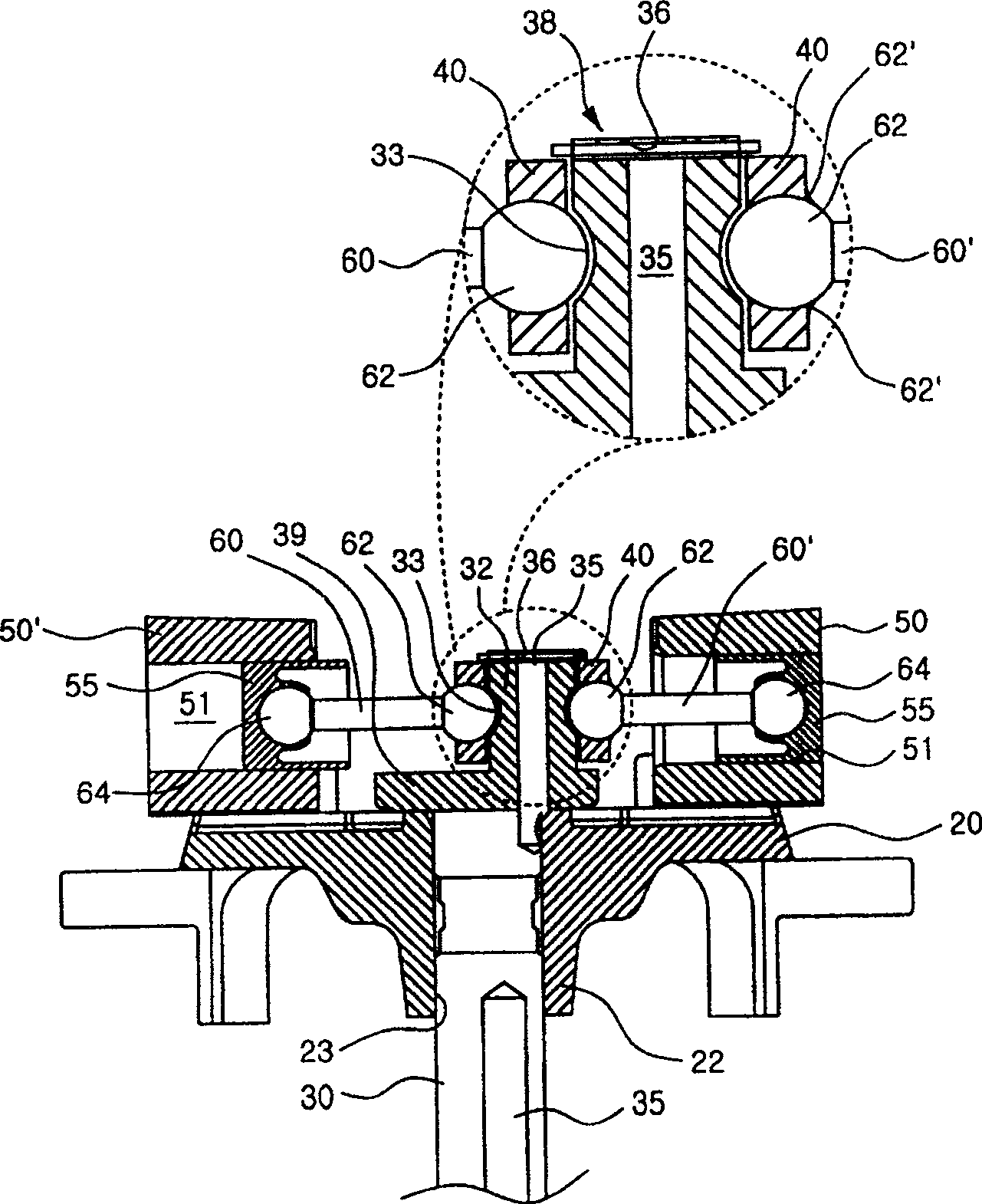
[0051] figure 2 It is an exploded oblique view of important parts of the multiple compressor embodiment of the present invention, image 3 It is a cross-sectional view of important parts of the embodiment of the present invention, Figure 4 It is a partial plan view of the structure of the embodiment of the present invention, and Fig. 5 is the structure of the connection cover of the embodiment of the present invention.

[0052] As shown in the figure, the rack 20 is installed inside the airtight container, and is a place where various components of the compressor are mounted. The frame 20 is generally spring supported inside the closed container. The central lower portion of the frame 20 is extended to form a hub [boss] portion 22 , and a communication hole 23 penetrating the frame 20 in the vertical direction is formed in the...


PUM


Abstract

The multi-compressor of the present invention is provided with a motor mechanism part and a plurality of compression mechanism parts driven by the motor mechanism part to compress the working fluid inside the airtight container, including a crankshaft, a cylinder, a connecting rod and a connecting cover. The crankshaft is provided with an eccentric pin that is eccentric relative to the rotation center; there are at least two cylinders, and the interior is formed as a compression chamber for compressing the working fluid. The ball end of each connecting rod is rotatably connected to the eccentric pin of the crankshaft. The outer peripheral surface of the eccentric pin forms a ball end installation groove for installing the ball end of the connecting rod end, and a ball end through portion is formed at the corresponding position of the connecting cover, and the ball end through portion is formed on one side of the connecting cover with an opening at the lower end. The multi-compressor of the present invention has the advantages of minimizing the operating noise of the compressor, significantly increasing the capacity of the compressor, increasing the efficiency of the compressor, and the like.

Description

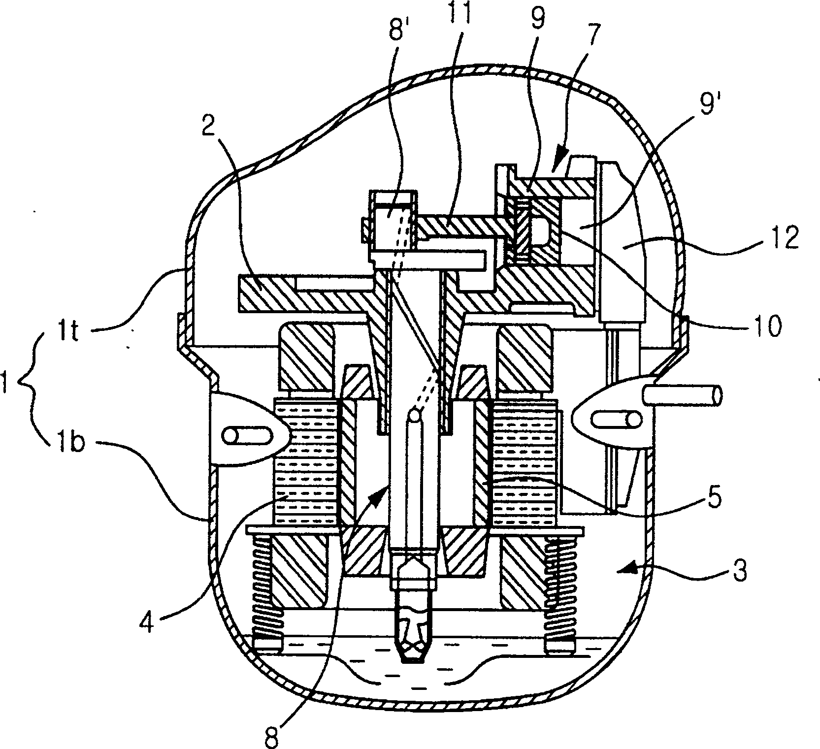
technical field [0001] The present invention relates to compressors, and more particularly, to multiple compressors formed with a plurality of compression chambers that compress working fluid. Background technique [0002] figure 1 It is a sectional view of a hermetic compressor structure in the prior art. As shown in the drawing, the airtight container 1 is composed of an upper container 1t and a lower container 1b, and forms a closed space inside. A rack 2 is provided inside the airtight container 1 . Various components of the compressor are mounted on the rack 2 . That is, the motor mechanism part 3 that supplies the driving force to the compressor and the compression mechanism part 7 that compresses the working fluid by using the driving force of the motor mechanism part 3 are mounted on the frame 2 . [0003] The motor mechanism unit 3 is composed of a stator 4 fixed to the frame 2 and a rotor 5 that rotates by an electromagnetic force generated between the stator 4...

Claims


Application Information

Patent Timeline
Patent Type & Authority Patents(China)
IPC IPC(8): F04B27/12F04B35/04
Inventor 朴圣云
Owner LG ELECTRONICS (TIANJIN) APPLIANCES CO LTD
Learn More