Heat exchanger and outdoor unit of air-conditioner having the same

A technology for heat exchangers and outdoor units, which is applied in the field of outdoor units, and can solve problems such as the decrease in the efficiency of heat sinks, the expansion of the temperature difference between the end of the heat sink and the surface of the heat transfer tube, and the increase in distance, so as to achieve improved heat dissipation and condensation performance, and heat transfer The effect of increasing the amount and improving the heat transfer performance

Inactive Publication Date: 2009-08-26
TOSHIBA CARRIER CORP
View PDF6 Cites 3 Cited by
  • Summary
  • Abstract
  • Description
  • Claims
  • Application Information

AI Technical Summary

Problems solved by technology

[0003] However, in the heat exchanger of Patent Document 1, since the diameter of the heat transfer tube is made small, the distance from the heat transfer tube to the end of the fin increases, and the temperature difference between the end of the fin and the surface of the heat transfer tube increases. There is a problem with the efficiency of the heat sink

Method used


Image

  • Heat exchanger and outdoor unit of air-conditioner having the same
  • Heat exchanger and outdoor unit of air-conditioner having the same
  • Heat exchanger and outdoor unit of air-conditioner having the same

Examples


Embodiment Construction

[0023] A heat exchanger according to an embodiment of the present invention will be described with reference to the drawings.

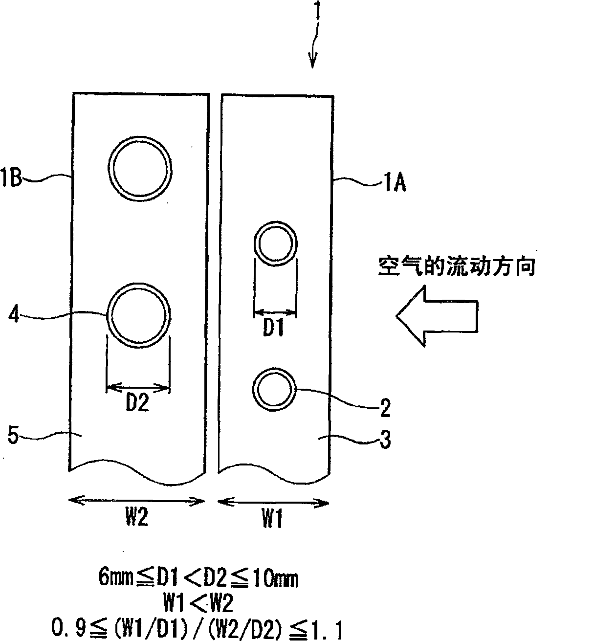
[0024] figure 1 It is a conceptual diagram of a heat exchanger according to an embodiment of the present invention.

[0025] like figure 1 As shown, the heat exchanger 1 of this embodiment is a fin-tube type heat-exchanger (fin-tubetype heat-exchanger), which has: an upper-wind side heat exchanger part 1A located on the upper side of the wind; The side heat exchanger unit 1A is separated from and disposed adjacent to the leeward side heat exchanger unit 1B located on the leeward side.

[0026] The upwind side heat exchanger unit 1A has small-diameter heat transfer tubes 2 as upwind heat transfer tubes arranged in a row in the airflow direction, and the small-diameter heat transfer tubes 2 are fitted side by side with a predetermined gap. A plurality of small-width cooling fins 3 that allow heat-exchanging air to flow along these gaps, and the cooli...


PUM


Abstract

The present invention provides a method for improving the heat transfer performance of the refrigerant flowing in the tube by making the diameter of the heat transfer tube on the upwind side smaller than that of the heat transfer tube on the downwind side, and even if the heat transfer performance on the upwind side is reduced. The diameter of the heat pipe can also prevent the efficiency of the heat sink from decreasing in the heat exchanger with high heat transfer performance. The heat exchanger has: two rows of heat transfer tubes arranged along the airflow direction; and a plurality of cooling fins arranged separately for each row of the two rows of heat transfer tubes and arranged side by side with a predetermined gap, so that the heat exchange air flows along these gaps, The relationship between the outer diameter D1 of the heat transfer tube on the upper side of the wind and the outer diameter D2 of the heat transfer tube on the lower side of the wind is set as 6mm≤D1<D2≤10.5mm. When the width of the lower fin is W2, the fin widths W1 and W2 are set so that 0.9≦(W1 / D1) / (W2 / D2)≦1.11.

Description

technical field [0001] The present invention relates to a heat exchanger and an outdoor unit of an air conditioner provided with the heat exchanger, and in particular to reducing the pressure loss of refrigerant flowing through two rows of heat transfer tubes arranged along the direction of air flow and improving the width of fins An optimized heat exchanger and an outdoor unit of an air conditioner having the heat exchanger. Background technique [0002] In general, in air conditioners, the cooling performance is emphasized, and the heat exchanger for outdoor units is set so that the flow of the refrigerant and the flow of air during condensation are reversed. At this time, since the refrigerant flowing through the heat transfer tubes on the windward side condenses faster than the refrigerant flowing through the heat transfer tubes on the downwind side, the refrigerant has a smaller specific volume and a smaller pressure loss. Therefore, conventionally, for example, in the...

Claims


Application Information

Patent Timeline
Patent Type & Authority Patents(China)
IPC IPC(8): F25B39/04F28F1/32
Inventor 大野裕司
Owner TOSHIBA CARRIER CORP
Why Eureka
Try Eureka