Automatic regulating arm for automobile braking

A technology for automatic adjustment of arms and automobile braking, applied in the field of transportation, can solve problems such as drag, inflexible adjustment, poor braking effect, etc., and achieve the effect of small resistance and flexible operation

Inactive Publication Date: 2009-09-02
韩兆瑞
View PDF10 Cites 0 Cited by
  • Summary
  • Abstract
  • Description
  • Claims
  • Application Information

AI Technical Summary

Problems solved by technology

The existing disadvantage of this kind of adjustment arm is that it belongs to intermittent adjustment firstly. Between two adjustments before and after, the distance between the brake pad and the brake hub is not always at the optimal distance, but changes from the optimal distance to the maximum allowable distance.
Therefore, there are cases where the braking effect is poor
The second is the maximum wear gap allowed between the brake pad and the brake hub, which is usually set according to the mileage or the feeling of the driver during the braking operation, and the deviation is large
It may cause the unclamping cam to be over-positioned or not reset, the brakes to be sluggish and dragged, the shoes and the brake hub not to be separated, and serious cases to cause fire and tire blowout
Based on the above-mentioned shortcomings of the adjustment arm that needs to be adjusted manually, some technical solutions for automatic adjustment appeared later, but there are still some shortcomings that affect actual use. Mechanical components have the same service life, and failures during use will directly affect driving safety
Other automatic adjustment schemes for mechanical structures are mostly adjusted during the braking process, the adjustment is not flexible enough, and the components wear out quickly

Method used


Image

  • Automatic regulating arm for automobile braking
  • Automatic regulating arm for automobile braking
  • Automatic regulating arm for automobile braking

Examples


Embodiment Construction

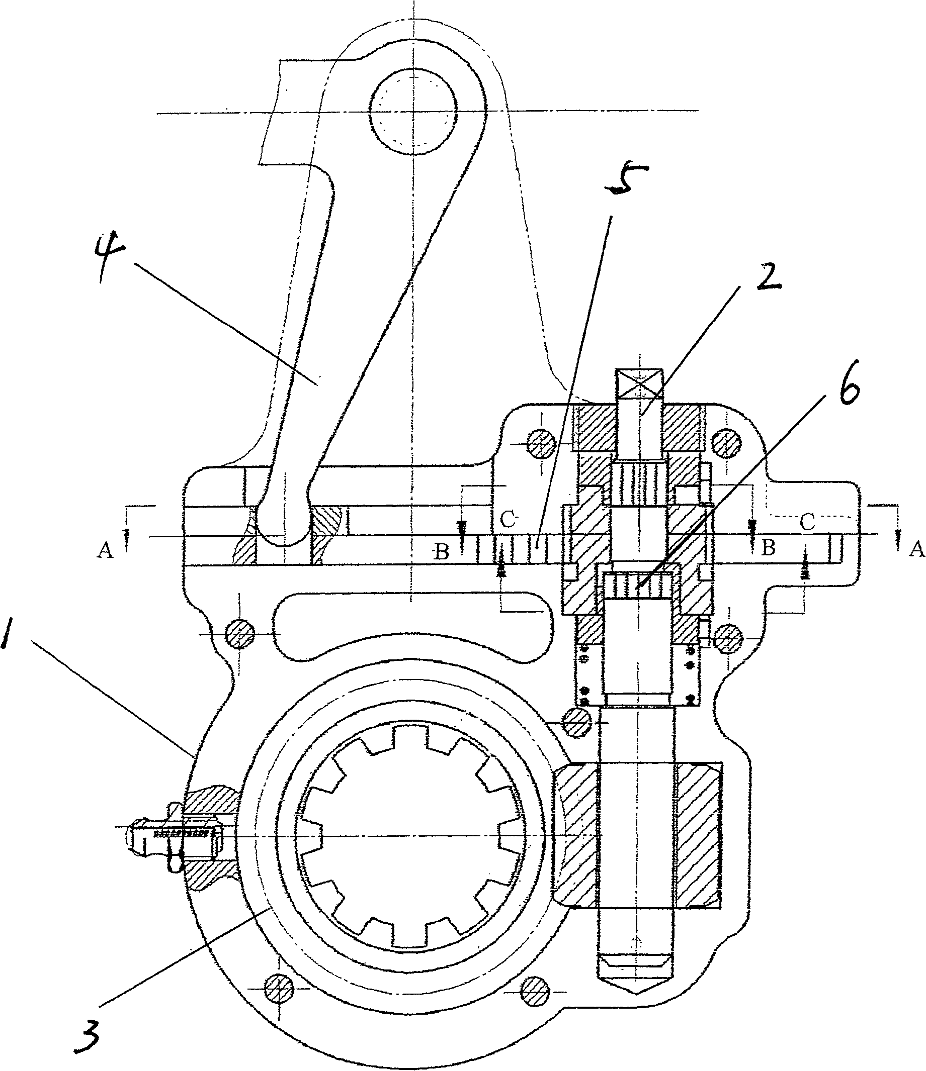
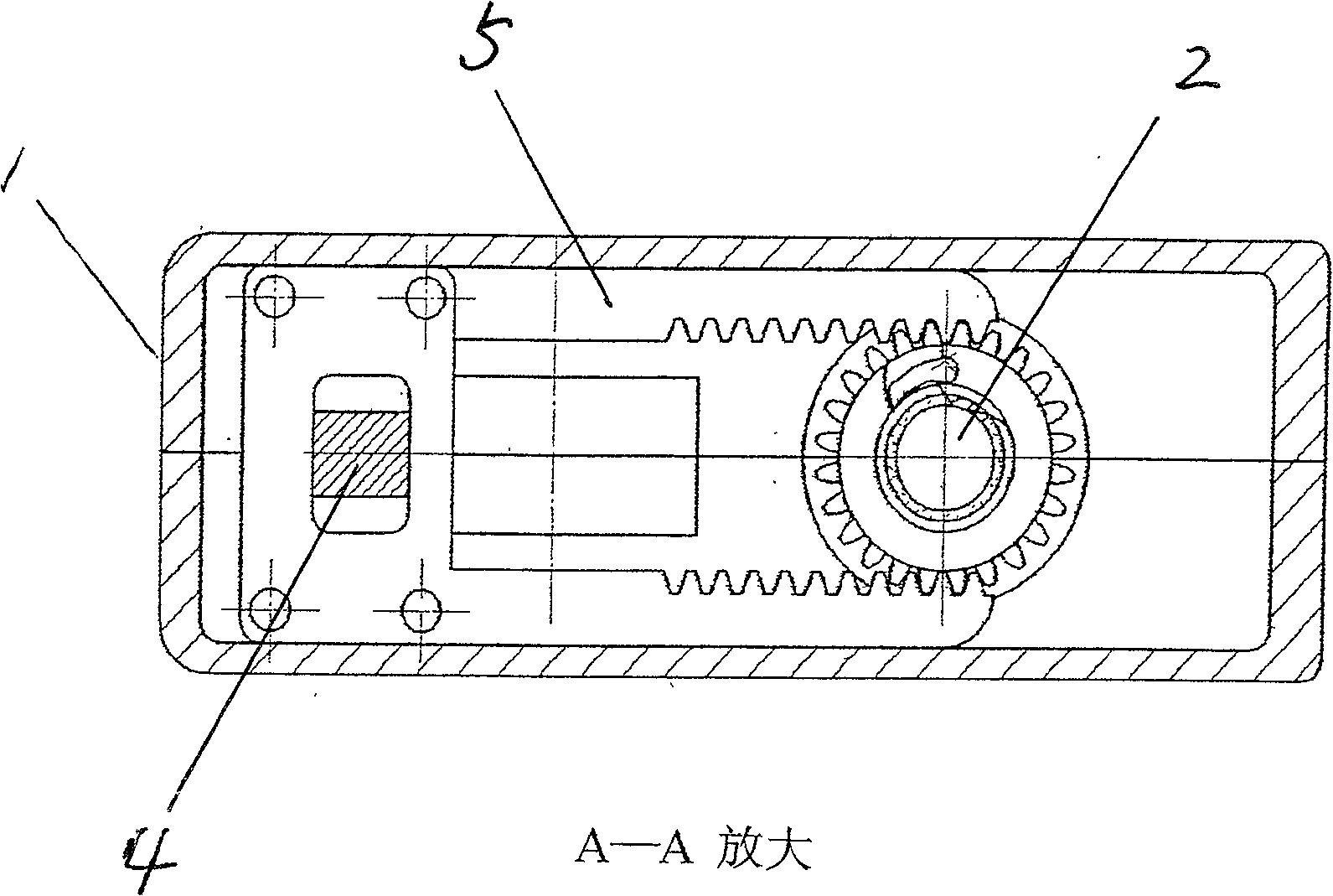
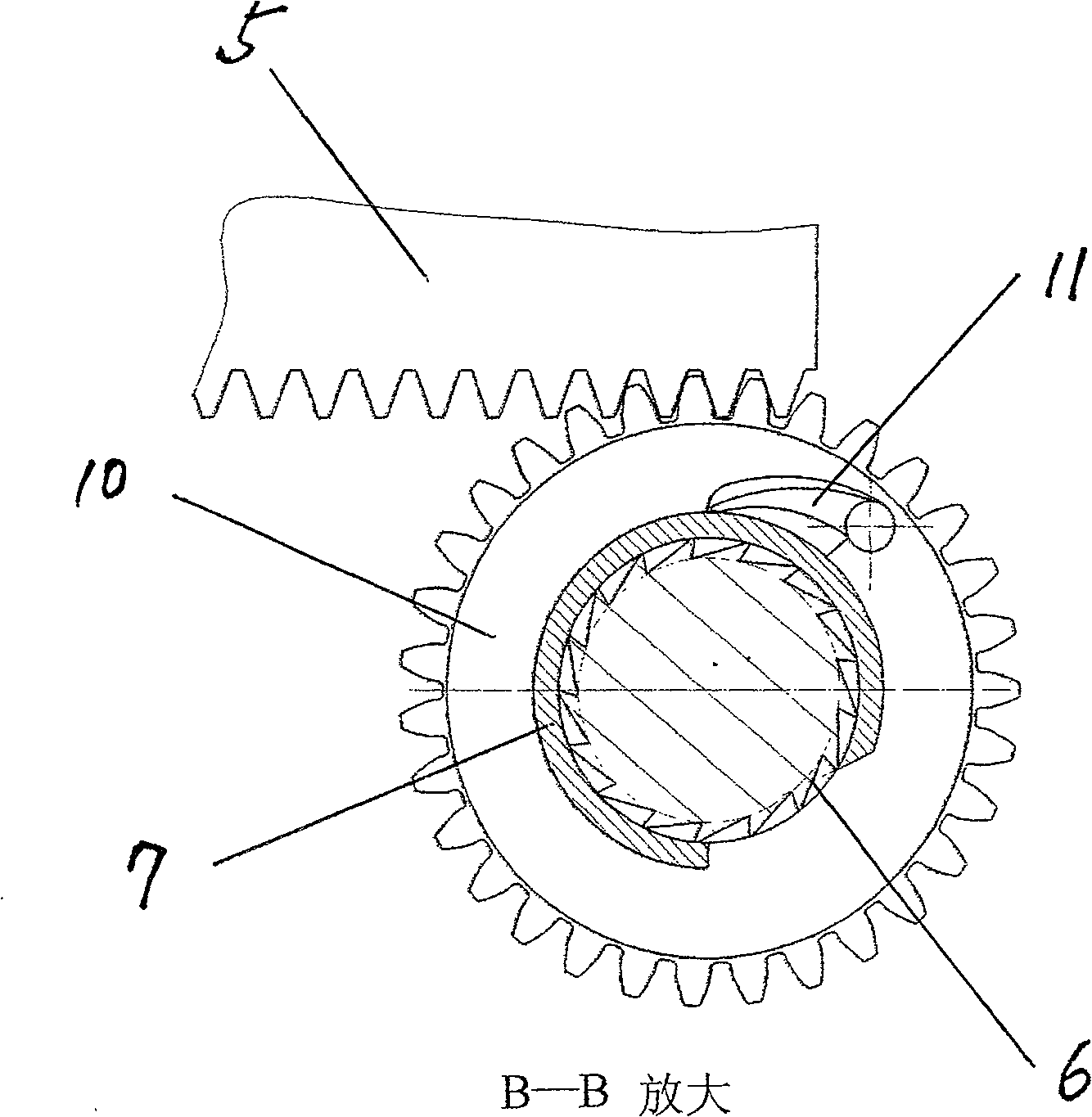
[0019] Embodiments of the present invention are given below in conjunction with the accompanying drawings.

[0020] made as figure 1 Shown is an adjustment arm comprising a housing 1 , a worm 2 , and a worm wheel 3 . Make the push rod and the adjustment arm as figure 1 Shown has the inflection shape of lever 4. Make one end to have two tooth bars 5 that driving rod stretches into hole, pack in the chute on the shell inner worm both sides housing. Two circles of ratchets 6 are processed on the worm, and the ratchets of the two circles of ratchets are obliquely opposite. Make the spacer sleeve 7 in the tubular thin-walled narrowing gap mechanism that axially has fracture and the spacer sleeve 8 in the expansion gap mechanism. The spacer 8 has a ring platform 8H and has a partially complete circumferential surface 8w. Put the spacer sleeve on the ratchet position on the worm. The isolation sleeve 7 is consolidated with the housing. The separating column 9 is fixed on the e...


PUM


Abstract

The utility model relates to an automatic brake adjustment arm of an automobile, which belongs to the technical field of transportation. It includes a housing, a worm gear cooperating with the brake camshaft in the housing, and an adjusting worm for driving the worm gear. The improvement is that there is a driving rod at the end of the pneumatic push rod. There are two racks inside the housing. There are ratchet teeth at the position of the upper rack of the worm, and a spacer sleeve with fractures on the peripheral surface of the ratchet teeth. Two adjusting gears meshed with the rack are respectively installed on the spacer sleeve. There is a ratchet on the adjusting gear. The spacer sleeve in the gap expansion mechanism has a complete section of the circumference and a ring platform, and a separation column is arranged on the ring platform. There is a boss on the gear. There is also a section of rib on the gear, and the first end of the rib is a slope corresponding to the position of the rib, and there is a telescopic spacer pin fixed on the housing. The positive effects of the invention are: automatic tracking adjustment; all mechanical parts are used, durable and trouble-free; adjustment in the return journey has small resistance, flexible operation, and no damage to components; the two-way adjustment function of both large and small adjustments is realized.

Description

technical field [0001] The invention belongs to the technical field of transportation, and in particular relates to an automobile braking device. Background technique [0002] In order to improve the driving safety of freight cars and large passenger cars using pneumatic brakes, it is important to maintain the best clearance between brake pads and brake hubs. For this reason, on the rotary arm that the braking camshaft of this type of automobile in the past connects pneumatic push rod, all is equipped with the adjustment, locking mechanism that is made up of worm screw and worm gear. By rotating the worm and rotating the worm wheel, the camshaft rotates at a corresponding angle relative to the rotating arm, increasing the radius of action of the cam on the shoe, and restoring the gap between the shoe and the brake hub to the initial set distance, forming what is now called adjustment. Components of the arm. Most of the adjustment methods provided by the existing adjustment...

Claims


Application Information

Patent Timeline
Patent Type & Authority Patents(China)
IPC IPC(8): F16D65/68
Inventor 韩兆瑞
Owner 韩兆瑞
Why Eureka
Try Eureka