Vacuum loading switch
What is Al technical title?
Al technical title is built by PatSnap Al team. It summarizes the technical point description of the patent document.
A vacuum load and switch technology, applied in electrical switches, high-voltage/high-current switches, high-voltage air circuit breakers, etc., can solve the problems of lowering the protection level of switch cabinets, assembly difficulties, and non-compliance with environmental protection requirements.
Active Publication Date: 2009-09-02
江苏德春电力科技股份有限公司
View PDF8 Cites 0 Cited by
Summary
Abstract
Description
Claims
Application Information
AI Technical Summary
This helps you quickly interpret patents by identifying the three key elements:
Problems solved by technology
Method used
Benefits of technology
Problems solved by technology
However, SF6 gas is a greenhouse gas, and its greenhouse effect is 2500 times that of carbon dioxide, which has a greater impact on the environment and does not meet environmental protection requirements.
In addition, the existing vacuum load switch adopts soft connection at the moving end of the vacuum interrupter and the connection end of the isolation knife switch. Since the soft connection is charged, the user can only add an insulating partition to separate the bus room and the cable room. The protection level of the switch cabinet is reduced, which brings inconvenience to the user; at the same time, due to the small installation space of the pole of the load switch, the guide gap of the moving end of the vacuum interrupter is also very small, and the vacuum interrupter's gap is small when fastening the soft connection. The bellows cannot bear force, so it is very difficult to assemble
Method used
Image
Click on the blue label to locate the original text in one second.
Reading with bidirectional positioning of images and text.
Examples
Embodiment Construction
[0015] The present invention is described in further detail below in conjunction with the embodiment that accompanying drawing provides.
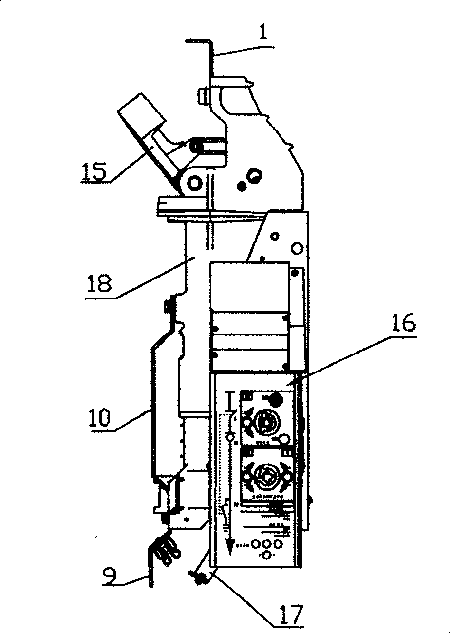
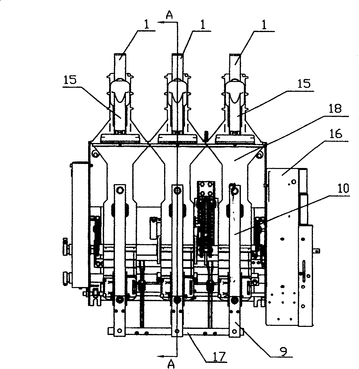
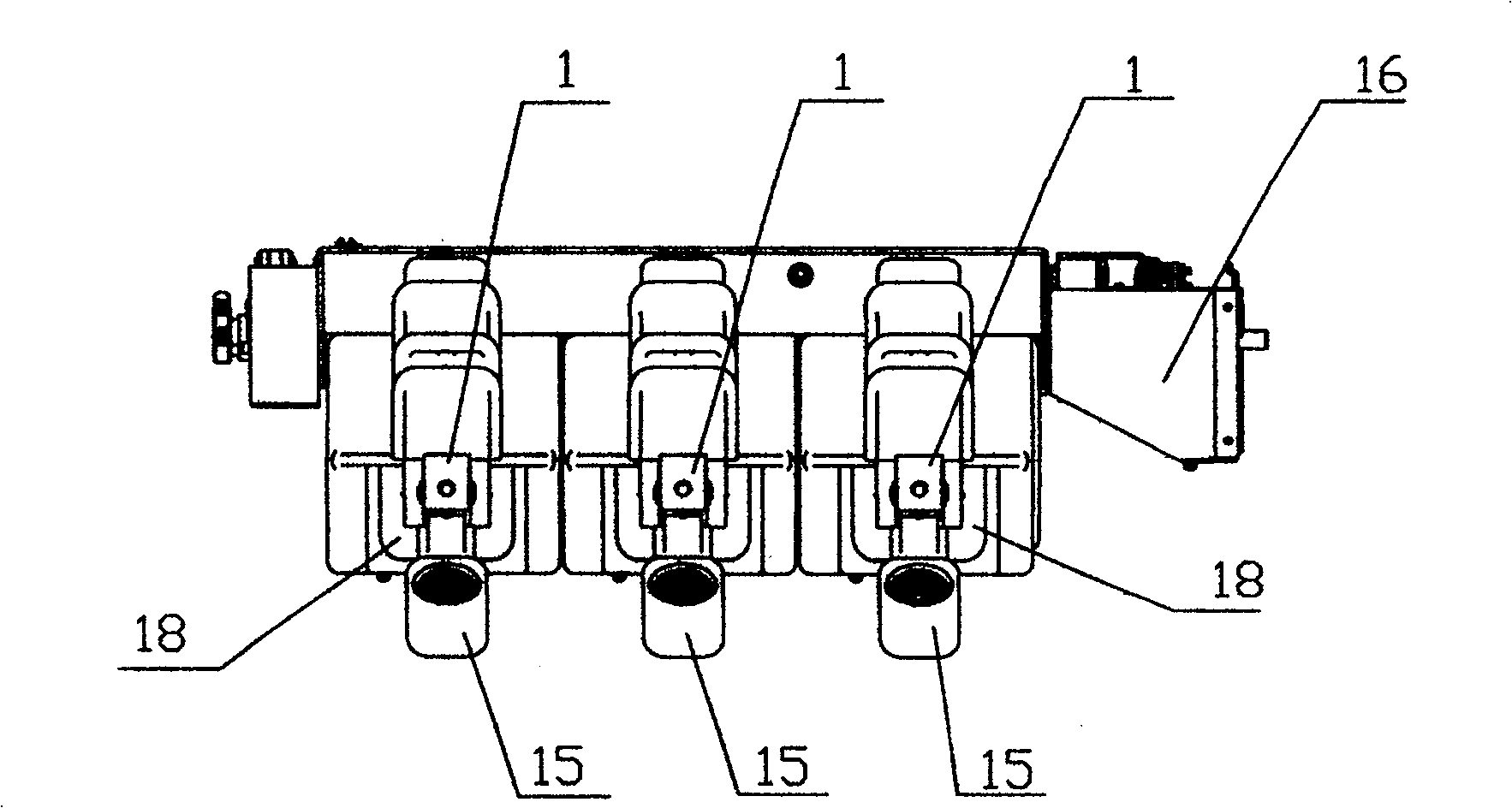
[0016] Such as figure 1 , 2 , 3, 4, and 5, a vacuum load switch of the present invention includes an upper outlet line 1 on a knife switch, an isolation knife switch 15, an isolation knife seat 13, a vacuum interrupter 5, a lower moving contact 11, and a lower outlet seat 12. Connection busbar 10, cable outlet plate 9, isolation knife insulation pull rod assembly 4, arc extinguishing chamber insulation pull rod assembly 8, operating mechanism 16 and grounding device 17, isolation knife switch 15 is connected in series with vacuum interrupter 5, isolation knife insulation The pull rod assembly 4 and the arc extinguishing chamber insulation pull rod assembly 8 are both connected to the operating mechanism 16 by transmission. The isolation knife seat 13, the vacuum interrupter 5 and the lower outlet seat 12 are solidly sealed together. Two c...
PUM
Abstract
The invention discloses a vacuum load switch for a high-voltage fixed switchgear, which includes an upper outgoing line of a knife switch, an isolation knife switch, an isolation knife seat, a vacuum interrupter, a lower moving contact, a lower outlet seat, and a connecting busbar , cable outlet plate, isolation knife insulation pull rod assembly, arc extinguishing chamber insulation pull rod assembly, operating mechanism and grounding device, isolation knife switch is connected in series with vacuum interrupter, isolation knife insulation pull rod assembly and arc extinguishing chamber insulation pull rod assembly are all connected with the operating mechanism Transmission connection, isolation knife seat, vacuum interrupter and lower outlet seat are solidly sealed together, the hinge end of the isolation knife switch is provided with a second contact finger spring, and the second contact finger spring is in contact with the isolation knife switch and the isolation knife seat respectively , There is a first contact finger spring at the moving end of the vacuum interrupter, and the first contact finger spring is respectively in contact with the lower moving contact and the lower outlet seat. The invention has high insulation strength, meets environmental protection requirements, is convenient to assemble and use, has high modularization level, and is suitable for standardized and large-scale production.
Description
technical field [0001] The invention relates to a high-voltage fixed switch cabinet, in particular to a vacuum load switch. Background technique [0002] The existing vacuum load switch, such as the ZN28-12 vacuum circuit breaker used in China, has exposed live parts, so it is greatly affected by the environment, has a high failure rate, and has low reliability. For this reason, the Chinese patent document CN1420514 discloses a vacuum automatic load switch on an integrated fully insulated pole, in which the operating mechanism, the isolation knife switch and the vacuum interrupter are all fixed in a sealed box filled with zero-gauge pressure SF6 gas. In order to prevent moisture intrusion and improve its reliability. However, SF6 gas is a greenhouse gas, and its greenhouse effect is 2500 times that of carbon dioxide, which has a great impact on the environment and does not meet environmental protection requirements. In addition, the existing vacuum load switch adopts soft ...
Claims
Application Information
Patent Timeline
Application Date:The date an application was filed.
Publication Date:The date a patent or application was officially published.
First Publication Date:The earliest publication date of a patent with the same application number.
Issue Date:Publication date of the patent grant document.
PCT Entry Date:The Entry date of PCT National Phase.
Estimated Expiry Date:The statutory expiry date of a patent right according to the Patent Law, and it is the longest term of protection that the patent right can achieve without the termination of the patent right due to other reasons(Term extension factor has been taken into account ).
Invalid Date:Actual expiry date is based on effective date or publication date of legal transaction data of invalid patent.