Combined helical fan flow mixing water distributor

A technology of stirring water distributor and fan flow, which is applied in the field of high-efficiency anaerobic treatment equipment, can solve the problems of not being given, narrow application range, etc., and achieve the effect of simple structure, low cost and operation cost, and favorable effects for survival

Inactive Publication Date: 2009-09-16
陈协
View PDF6 Cites 0 Cited by
  • Summary
  • Abstract
  • Description
  • Claims
  • Application Information

AI Technical Summary

Problems solved by technology

But its disadvantages are: A. It is limited to the most basic frame of the water distributor of MEIC, and the applicable surface is narrow
B. Without the basic framework given, the general preferred specific structure of this kind of water distributor

Method used


Image

  • Combined helical fan flow mixing water distributor
  • Combined helical fan flow mixing water distributor
  • Combined helical fan flow mixing water distributor

Examples


Embodiment 1

[0033] Example 1: A cylindrical high-efficiency anaerobic reactor with a diameter of 6m≤D≤16m

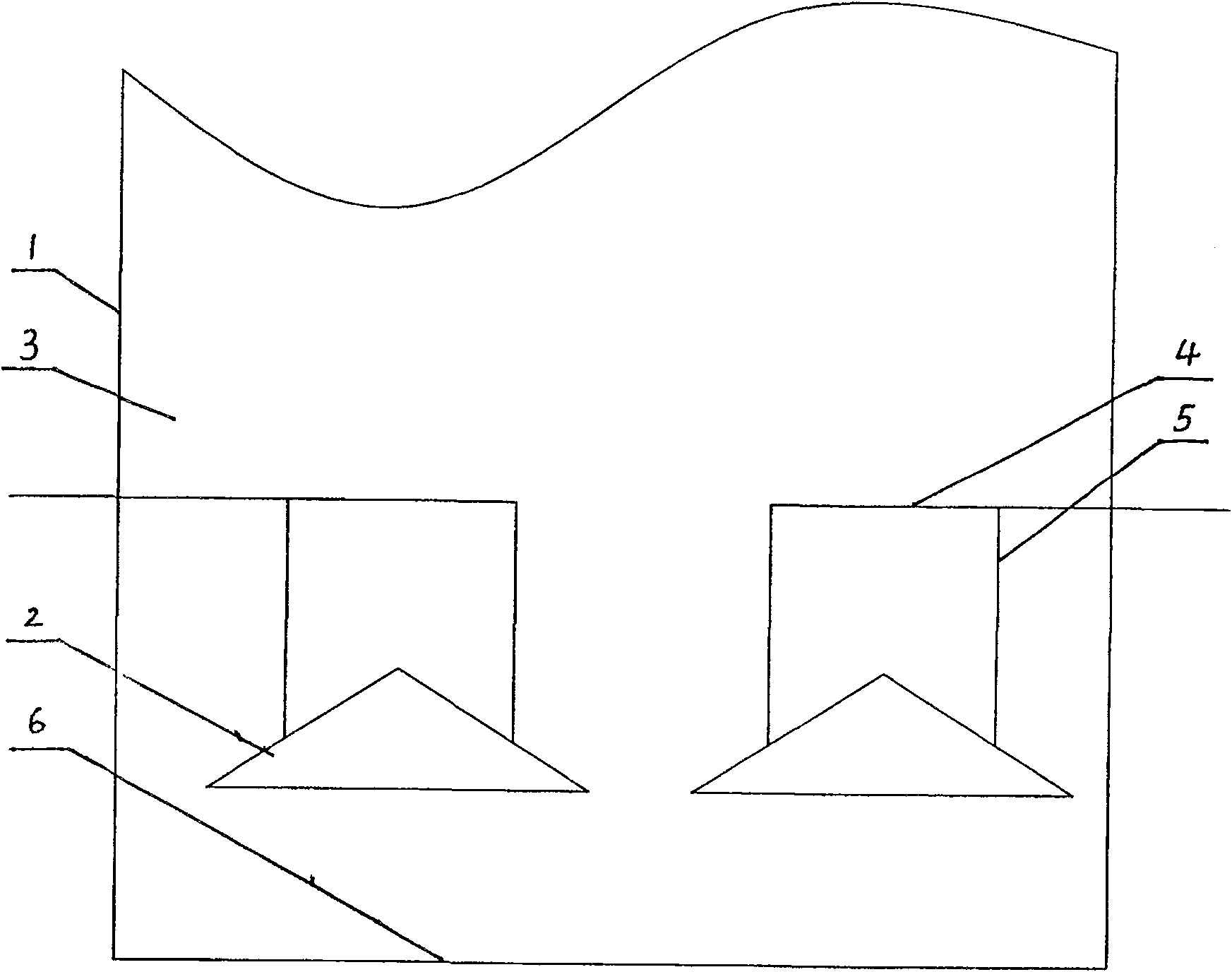
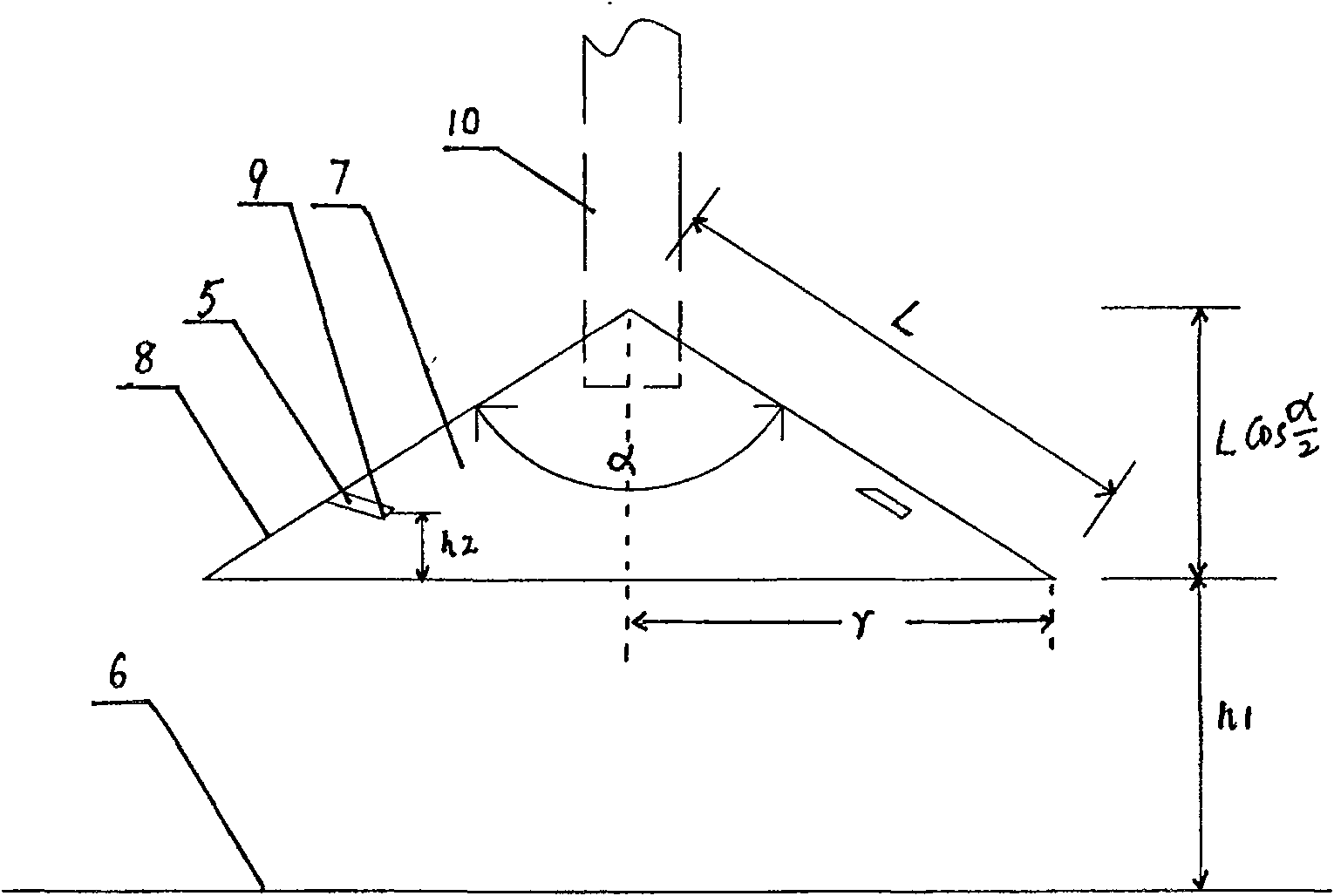
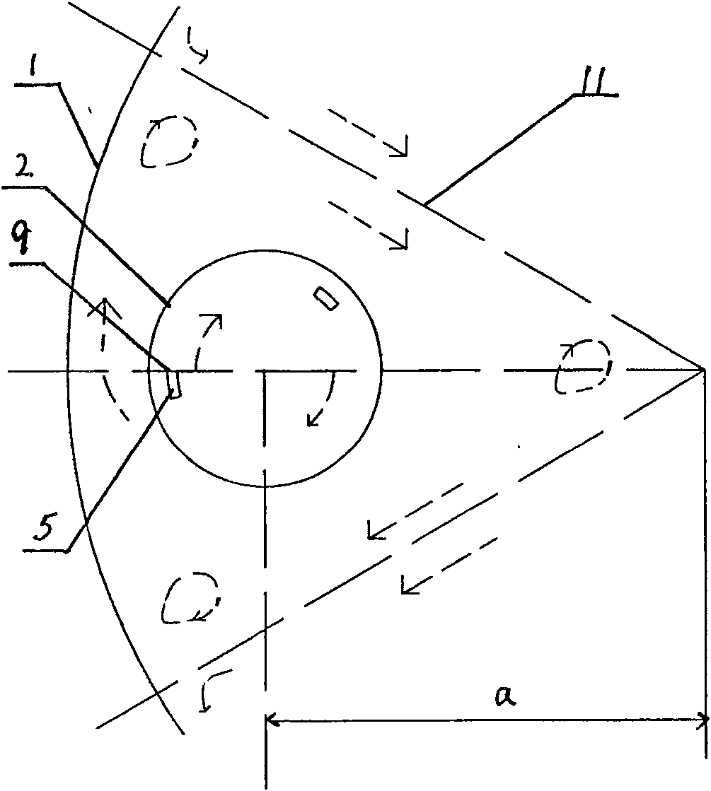
[0034] The present invention comprises the swirl hood 2 installed at the lower part of the lower reaction chamber 3 in the reactor housing 1, one end of the waste water input pipe 4 above the swirl hood 2 is connected to the waste water main pipe, and the other end passes through the reactor housing 1. The side wall enters the lower reaction chamber 3 and connects to the waste water input branch pipe 5, and there are 4 uniformly distributed at a distance from the center of the reactor, the apex angle of the axis plane is α, the side length is L, and the bottom radius is r ( r = Lsim α 2 ) , The height from the bottom to the bottom of the anaerobic reactor shell is h 1 The swirl hood 2.

[0035] Each swirl hood 2 has 2-4 waste ...

Embodiment 2

[0065] Example 2: A cylindrical high-efficiency anaerobic reactor with a diameter of 12m≤D≤28m

[0066] The structure of embodiment 2 is basically the same as embodiment 1, the difference is:

[0067] There are 6 evenly distributed at a distance from the center of the reactor, the axis plane vertex angle is α, the side length is L, and the bottom radius is r ( r = Lsim α 2 ) , The height from the bottom to the bottom of the anaerobic reactor shell is h 1 The swirl hood 2.

[0068] Each swirl hood 2 has 3-5 waste water input branch pipes 5, the upper ends of the 3-5 waste water input branch pipes 5 are all connected to the waste water input pipe 4, and the lower ends of the 3-5 waste water input branch pipes 5 pass through the swirl hood vertically respectively 2. The height from the bottom of the swirl hood 2 is h 2The outlet 9 of the wast...


PUM

PropertyMeasurementUnit
diameteraaaaaaaaaa
diameteraaaaaaaaaa
diameteraaaaaaaaaa

Abstract

The invention discloses a water distributor for combined spiral fan-current stirring, comprising a swirl mask and an intake pipe for sewage. The invention is characterized in that: 1. four swirl masks (the diameter thereof is more than or equal to 6 m and less than or equal to 16 m), or six swirl masks (the diameter thereof is more than or equal to 12 m and less than equal to 28 m) are evenly distributed at the places with a distance of a to the center of the reactor; the apex angle of the shaft plane thereof is alpha; the side length is L, the radius of the bottom is r and the height from the bottom to the bottom part of the enclosure of an anaerobic reactor is h1. 2. the lower parts of two to four wastewater intake branches (the diameter thereof ranges from 6m to 16m) or three to five wastewater intake branches (the diameter thereof ranges from 12m to 28m) vertically go through the swirl masks respectively. The outlets of the wastewater intake branches with same diameter, same swirl-flow direction and forming an angle beta downwards with the level in the shearing direction are arranged evenly on the place of the internal wall and keeping a distance of h2 from the mask bottom to enable the swirl generated by wastewater to keep in the same direction. 3. the swirl flow direction formed by a plurality of swirl masks enables the intersection of any two swirls to keep the same flow direction. The invention has the advantages of high effective stirring and mixing, being beneficial to enhancing mass transfer in reaction zones and the existence of granular sludge, simple structure, low manufacturing and operation cost.

Description

technical field [0001] The invention relates to high-efficiency anaerobic treatment equipment, in particular to a combined spiral fan flow stirring water distributor used for high-efficiency anaerobic reactors. Background technique [0002] The second-generation anaerobic reactor represented by the upflow anaerobic sludge bed (UASB) adopts a three-phase separator to realize the separation of mud and water retention time, and under certain conditions, it can realize the separation of granular sludge The growth of the anaerobic digestion technology has undergone fundamental changes, and the anaerobic technology has entered an era of high efficiency. At the same time, the emergence of granular sludge makes the wastewater reach a medium flow rate relative to the sludge, and the granular sludge is still in the fluidization stage, thus greatly improving the mass transfer effect. The third generation of anaerobic reactors, represented by anaerobic expanded granular sludge bed (EGS...

Claims


Application Information

Patent Timeline
Patent Type & Authority Patents(China)
IPC IPC(8): C02F3/28
Inventor 陈协
Owner 陈协
Why Eureka
Try Eureka