Eureka AIR delivers breakthrough ideas for toughest innovation challenges, trusted by R&D personnel around the world.

Throwing type high energy gas fracturing device

A high-energy gas fracturing and delivery-type technology, which is applied in the direction of production fluid, wellbore/well components, earthwork drilling and production, etc., can solve the problems of increased construction cost, difficulty, and large error of accumulated shear force, etc., and achieve operational The effect of low success rate, high operation success rate and high control precision

Active Publication Date: 2009-09-30
XIAN TONGYUAN PETROTECH
View PDF6 Cites 0 Cited by
  • Summary
  • Abstract
  • Description
  • Claims
  • Application Information

AI Technical Summary

Problems solved by technology

This process has the following defects: 1) The high-temperature and high-pressure gas formed after the fracturing bomb is burned causes the cable to be ablated; 2) The cable is lifted up and knotted, especially for the oil pipeline transportation operation, and the cable knot has a great impact on the construction ; 3) Construction operations need to be equipped with equipment such as cable cars and positioning instruments, and the construction cost increases
The launch type fracturing device determines the fracturing at the predetermined position through the relationship between the fluid pressure in the well and the shear resistance of the piston fixing pin, but in fact, due to the influence of processing, assembly and material itself, each fixing pin It is difficult to achieve accurate control of the shear resistance, and it is even more difficult to cut several fixed pins at the same time. Once several fixed pins are sheared at inconsistent times or the error of the accumulated shear force is large, this The method of using the shear resistance of fixed pins to control the location of fracturing will lose its meaning
In addition, the shearing process time of the fixed pin is also relatively long
Therefore, the response speed of this delivery type fracturing device is slow, the precision is low, the error is large, and it is easy to fail

Method used


Image

  • Throwing type high energy gas fracturing device
  • Throwing type high energy gas fracturing device

Examples


Embodiment Construction

[0011] The content of the present invention will be described in detail below in conjunction with the accompanying drawings and embodiments.

[0012] Such as figure 1 As shown: the fracturing device is composed of an ignition device 2 , an output joint 3 of the ignition device, a fracturing bomb 4 , an intermediate joint 5 and a tail plug 6 connected in sequence. In order to facilitate cleaning the bottom of the well after fracturing, a T-shaped fishing head 1 is connected to the upper end of the ignition device 2, and the T-shaped fishing head 1 can be grasped by movable claws, thereby taking out the wreckage.

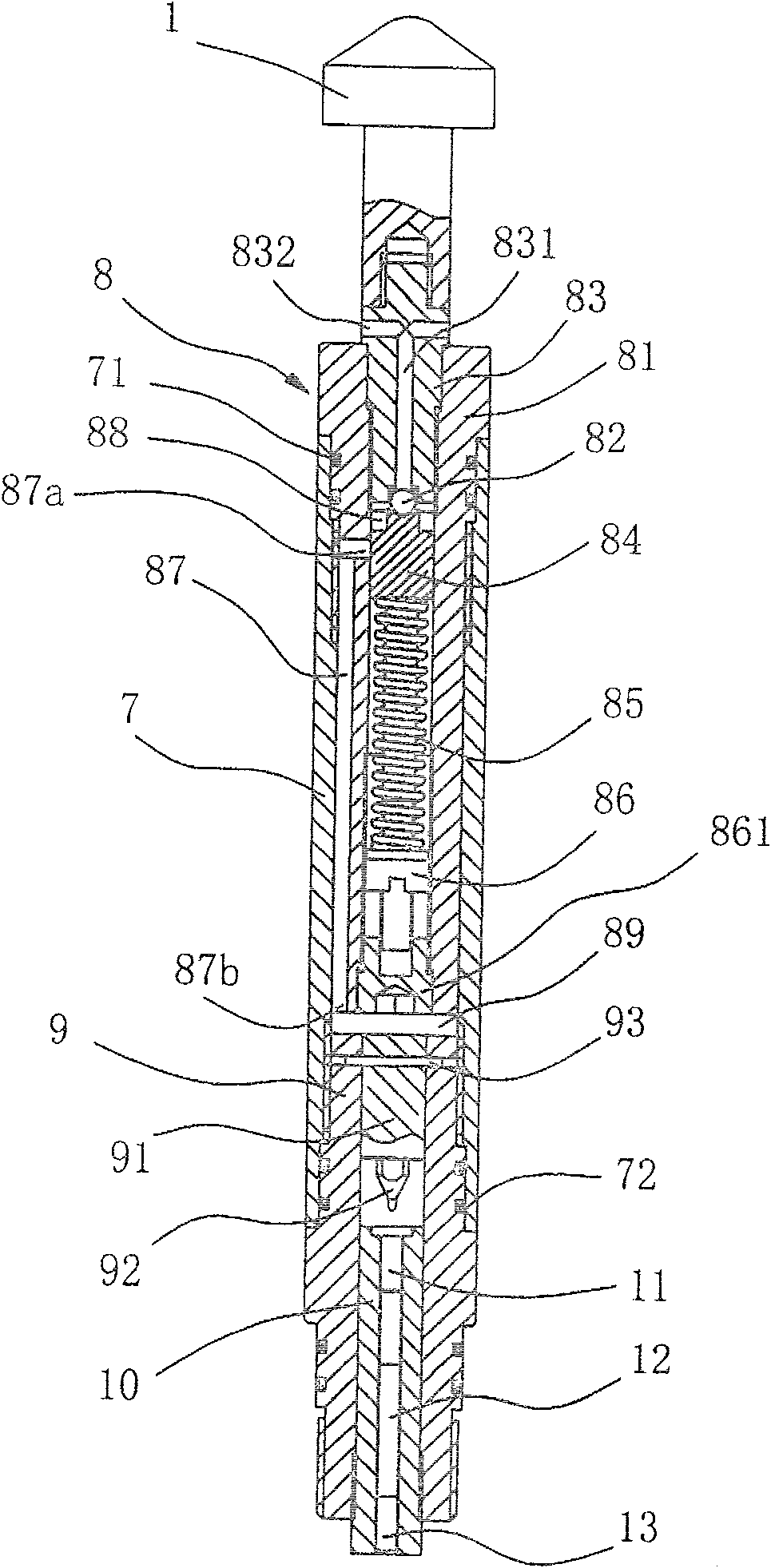
[0013] Such as figure 2 Shown: ignition device 2 is cylindrical, is mainly made up of shell 7, T-shaped salvage head 1, the pilot valve 8 that opens with spring control, the striker piston 91 that is contained in striker barrel 9 and ignition core seat 10 etc. composition. Among them, the pilot valve 8 and the striker cylinder 9 are respectively connected to the up...


PUM


Abstract

The invention belongs to oil and gas well stimulation technology, and is a drop-in high-energy gas fracturing device. It includes an ignition device and a fracturing bomb connected to the ignition device. The ignition device includes a firing pin piston installed in the barrel and an excitation device for the firing pin. The firing pin piston is connected to the barrel through a radial fixing pin. The detonator of the fracturing bomb Or the primer is located at the bottom of the aforementioned barrel and corresponds to the firing pin; the special feature of the present invention is that the triggering device of the firing pin includes a pilot valve controlled by a spring, the inlet of the pilot valve communicates with the outside world, and a connection The first port of the pipe is located at the outlet of the pilot valve, and the second port of the connecting pipe communicates with the airtight cavity at the tail end of the striker piston. The invention uses a spring to control the opening of the pilot valve, and then leads the wellbore fluid to the striker piston, which not only has fast response, high control precision, but also reliable operation and high operation success rate.

Description

technical field [0001] The invention belongs to oil and gas well stimulation technology, in particular to a drop-in high-energy gas fracturing device. Background technique [0002] For production wells or old wells in oilfields, with the increase of production time, the geological conditions around the original perforated section of the oil layer will continue to change. In addition to the potential pollution to the formation caused by the drilling and completion process before putting into production, after the oil well is put into production, the crude oil in the oil layer enters the perforation tunnel through rock pores, natural fractures or artificial fractures. During this process, organic matter, polymers, and downhole microorganisms and bacteria in the oil layer will gradually accumulate to block the pores and fractures near the wellbore, resulting in poor permeability of the near wellbore, resulting in a gradual decrease in oil production and shutdown the result of....

Claims


Application Information

Patent Timeline
Patent Type & Authority Patents(China)
IPC IPC(8): E21B43/263
Inventor 张国桉成建龙
Owner XIAN TONGYUAN PETROTECH
Why Eureka
Eureka Blog
Learn More