Optical recording medium, recording method thereof and evaluation method of optical recording medium

A technology of optical recording medium and recording method, applied in the direction of optical recording/reproduction/erasing method, optical recording head, optical recording system, etc., capable of solving problems such as recording difficulties

Inactive Publication Date: 2009-09-30
RICOH KK
View PDF6 Cites 0 Cited by
  • Summary
  • Abstract
  • Description
  • Claims
  • Application Information

AI Technical Summary

Problems solved by technology

Therefore, if a recording layer material capable of corresponding to high-speed recording is used, there is a problem that recording becomes very difficult at any recording speed lower than the highest recording speed.

Method used


Image

  • Optical recording medium, recording method thereof and evaluation method of optical recording medium
  • Optical recording medium, recording method thereof and evaluation method of optical recording medium
  • Optical recording medium, recording method thereof and evaluation method of optical recording medium

Examples


Embodiment 1

[0179] Since there is no DVD medium corresponding to high-speed recording of 20 m / s or higher on the market, a sample disk was made.

[0180] will be composed of ZnS and SiO 2 The 60nm thick lower protective layer made of the mixture of GaSbSnGe alloy, the 15nm thick recording layer made of ZnS and SiO 2 A 10-nm-thick upper protective layer made of a mixture of Ag and a 200-nm-thick reflective layer made of Ag are sequentially laminated on a 0.6 mm-thick and 120-mm-diameter polycarbonate DVD+RW substrate with a sputtering process. A spiral continuous group with a track pitch of 0.74 μm. Also, another substrate was adhered on the reflective layer by a commercially available UV resin adhesive for disks to make it a 1.2 mm thick disk. Its shape fully meets the DVD+RW specification.

[0181] Subsequently, the recording layer is crystallized over the entire surface by an initiation device for a phase-change type disk. Produced disc is good and meets various specifications of DV...

Embodiment 2

[0203] For the same sample tray as in Example 1, the recording was performed by using the same method as in Example 1, except that the parameters in Table 3 were used instead of Table 1.

[0204] table 3

[0205] speed

Scanning speed v(m / s)

Clock cycle T(ns)

T LP3 / T

T CP3 / T

3.3×

11.52

11.6

0.313

2.125

4.0×

13.96

9.6

0.328

1.850

5.0×

17.45

7.6

0.344

1.575

6.0×

20.94

6.4

0.359

1.300

6.0×

20.94

6.4

0.625

1.300

7.0×

24.43

5.5

0.656

1.025

8.0×

27.92

4.8

0.688

0.750

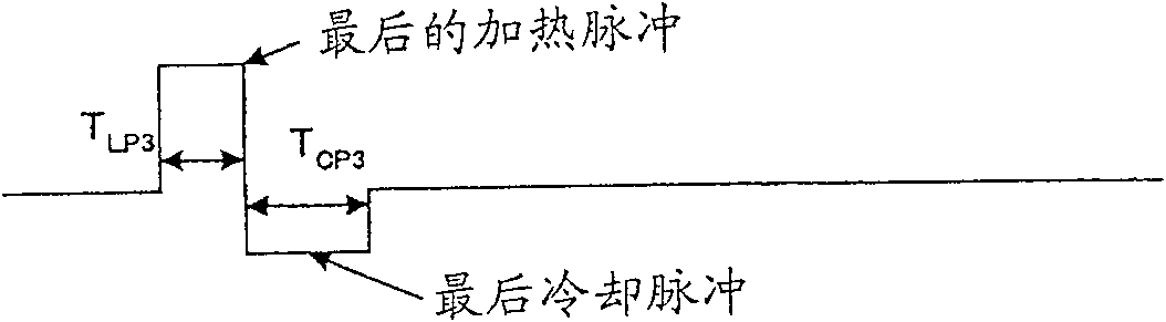
[0206] Parameter T LP3 and T CP3 The correlation with scan speed is shown in Figure 12 . T CP3 Use a continuous function to determine, but T LP3 Use two functions to determine. That is, at v0 within the range of T LP3 / T=g 1,3 (v)=0.00489v+0.258; when ...

Embodiment 3

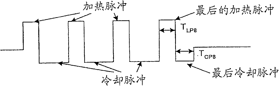
[0210] For the same sample disc as in Example 1, the recording was performed in the same manner as in Example 1, except that a pattern with alternating 10T marks and 10T gaps was recorded by a 2T strategy with n=10 and m=5 and using the table In addition to the parameters in 4. Here, the length of the heating pulse was made the same as that of the last heating pulse, and the same value as in Example 1 was set.

[0211] Table 4

[0212] speed

Scanning speed v(m / s)

Clock cycle T(ns)

T LP3 / T

T CP3 / T

3.3×

11.52

11.6

0.313

1.875

4.0×

13.96

9.6

0.375

1.750

5.0×

17.45

7.6

0.438

1.625

6.0×

20.94

6.4

0.500

1.500

6.0×

20.94

6.4

0.500

0.500

7.0×

24.43

5.5

0.563

0.250

8.0×

27.92

4.8

0.625

0.000

[0213] Parameter T LP10 and T C...


PUM

PropertyMeasurementUnit
wavelengthaaaaaaaaaa

Abstract

A recording method for an optical recording medium, comprising: irradiating the medium with a laser light having m pulse groups, wherein each pulse group includes a heating pulse and a cooling pulse, wherein m is a natural number; The above medium is used to record marks with a length of nT, wherein n is a natural number of 3 or more, and T is a clock period, wherein the length TCPn of the last cooling pulse is determined according to the scanning speed v using the following function: when v<v0, TCPn / T=f1, n(v); when v≥v0, TCPn / T=f2, n(v), where f1, n(v) and f2, n(v) all represent continuous functions of scanning speed v , and satisfy the condition that the presence ratio of abnormal markers is 1.0×10⁻⁴ or less, and v0 is a selectable scanning speed.

Description

technical field [0001] The present invention relates to a rewritable optical recording medium such as CD-RW, DVD-RW, DVD+RW, DVD-RAM etc. using a phase change material in the recording layer, a recording method of the optical recording medium and the optical recording medium Media evaluation methods. Background technique [0002] It is known to set parameters for the recording speed by a linear function (see Patent Documents 1 to 3). In particular, techniques for gradually changing parameters have been disclosed in Patent Documents 2 and 3. [0003] However, there is no mention that the length (irradiation time) of at least any one of the final heating pulse and the final cooling pulse is changed discontinuously. [0004] Rewritable discs to which phase change technology is applied, represented by CD-RW, DVD-RW, DVD+RW, etc., are widely used for audio / visual purposes and information recording purposes for computers. Furthermore, improvements in recording speeds and increa...

Claims


Application Information

Patent Timeline
Patent Type & Authority Patents(China)
IPC IPC(8): G11B7/0045G11B7/125G11B7/0037G11B7/006
Inventor 加藤将纪伊藤和典出口浩司大仓浩子安部美树子关口洋义
Owner RICOH KK
Why Eureka
Try Eureka