Differential valve

A technology of valve body and spool valve core, which is applied to broaching devices, mechanical equipment, broaching machines, etc. It can solve the problems of reducing the working efficiency of broaching machines and achieve the effect of increasing the moving speed

Active Publication Date: 2009-10-07
CHAGYI LIHUI BROACHING MACHINE MAFACTURE
View PDF4 Cites 2 Cited by
  • Summary
  • Abstract
  • Description
  • Claims
  • Application Information

AI Technical Summary

Problems solved by technology

From the perspective of improving work efficiency, the return time of the broach should be as short as possible. However, in the known technology, when the broach returns, the rodless chamber of the hydraulic cylinder is a high pressure chamber, and the rod chamber is a low pressure chamber. When the broach is broaching, the rod chamber of the hydraulic cylinder is a high-pressure chamber, and the rodless chamber is a low-pressure chamber. Since the effective cross-sectional area of ​​the rodless chamber is larger than that of the rod chamber, at the same flow rate Under the circumstances, the return speed of the broach is lower than the cutting feed speed of the broach, in other words, the return time of the broach is longer than the broaching time of the broach, which greatly reduces the working efficiency of the broach

Method used


Image

  • Differential valve
  • Differential valve
  • Differential valve

Examples


Embodiment Construction

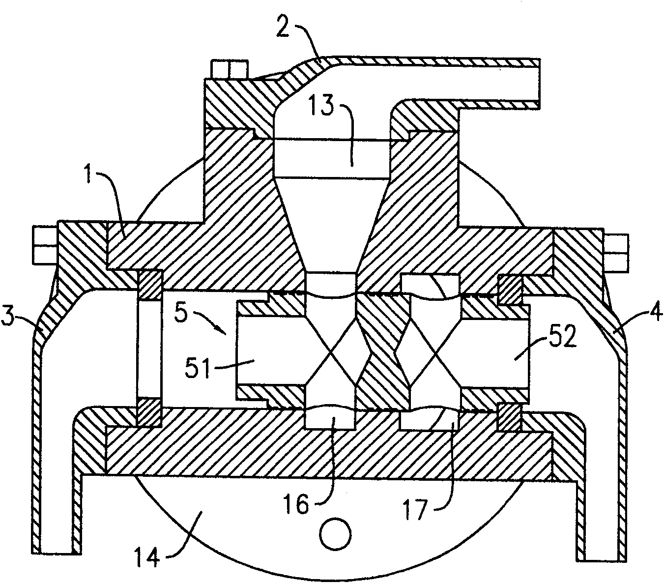
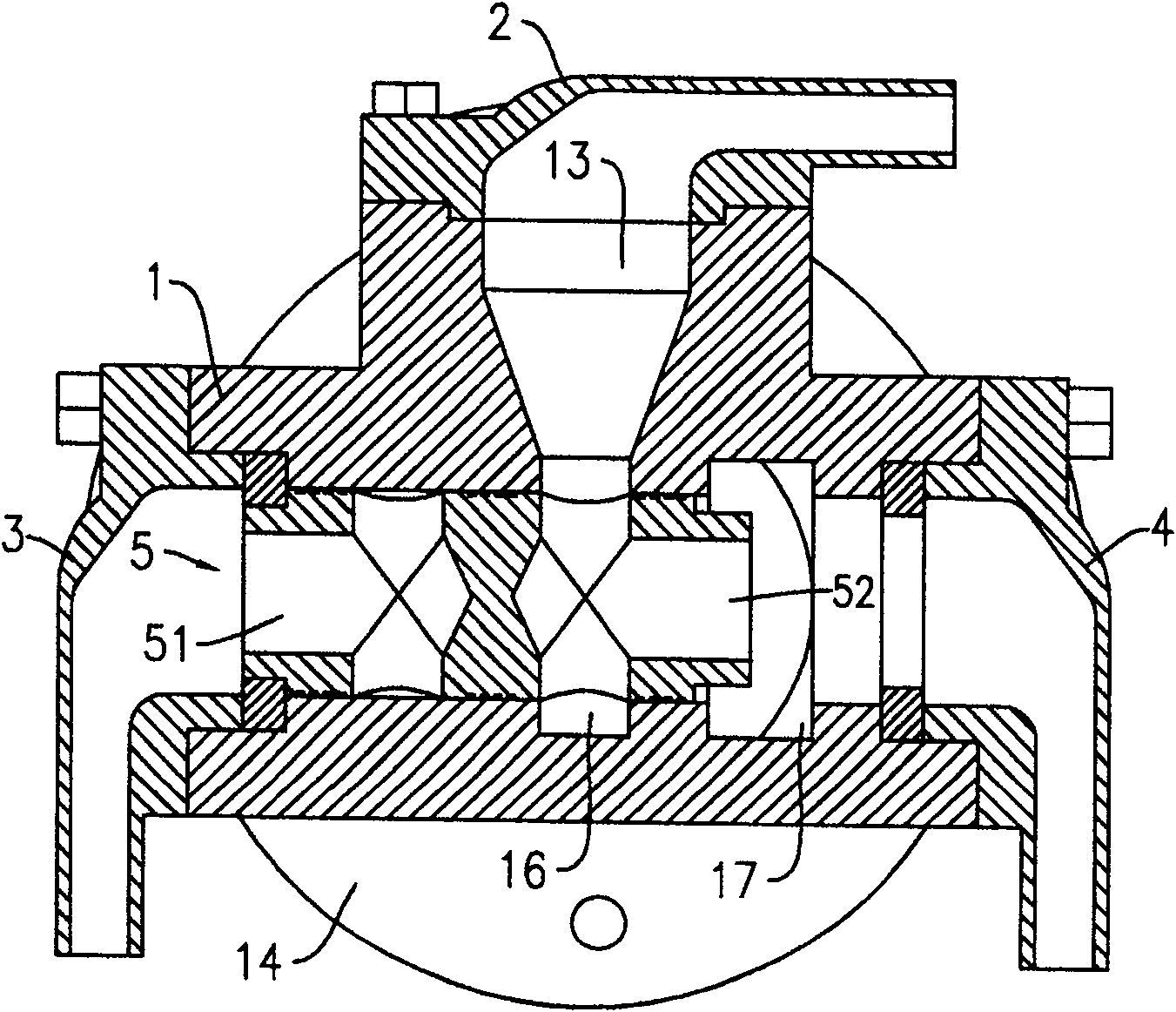
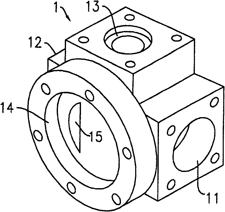
[0010] A differential valve such as figure 1 and image 3 As shown together, the inside of the valve body 1 is provided with a slide valve cavity, and a slide valve core 5 is installed in the slide valve cavity. The valve body 1 is provided with a first liquid control port 11 and a second liquid control port 12 , a first liquid port 13 and a second liquid port 14 . The first liquid control port gland 3 is fixed on the first liquid control port 11, which can be connected with a liquid port of the reversing valve, and the second liquid control port gland 4 is fixed on the second liquid control port 12, which can be connected with the second liquid control port 12. The other liquid port of the reversing valve is connected, the first liquid port gland 2 is fixed on the first liquid port 13, and can be connected with the rod chamber of the hydraulic cylinder, and the second liquid port 14 can be connected with the hydraulic cylinder Rodless cavity connection. The first hydraulic...


PUM


Abstract

The invention discloses a differential valve, the main technical point of which is that a first flow path and a second flow path which are not communicated with each other are arranged on the slide valve core; when the slide valve core is in the first working position, the valve body The first liquid control port of the valve body communicates with the first liquid port of the valve body through the first flow path of the spool valve core, and the second liquid control port of the valve body communicates with the second liquid port of the valve body through the second flow path of the spool valve core. When the spool is in the second working position, the second liquid control port of the valve body is directly connected with the second liquid port of the valve body, and the second liquid control port of the valve body passes through the second liquid control port of the spool The flow path communicates with the first liquid port of the valve body. Without changing the flow rate of the hydraulic pump, the moving speed of the hydraulic cylinder piston can be increased by more than two times. If this differential valve is installed on a horizontal broaching machine, the return time of the broach will be greatly shortened, and the broaching speed will be improved. bed efficiency.

Description

technical field [0001] The invention relates to the technical field of valves, in particular to a valve that enables hydraulic cylinder pistons to have different movement speeds when high-pressure oil is respectively fed into a rod chamber or a rodless chamber of a hydraulic cylinder. Background technique [0002] For a horizontal broaching machine, the broach is fixed together with the piston rod of the hydraulic cylinder through a collet. Under the control of the hydraulic system, the broaching operation is realized when the piston rod retracts, and the broaching operation is realized when the piston rod is extended. return. Since the broach and the piston rod are pulled when retracting, the rigidity is good and it is not easy to deform, so the accuracy of the workpiece can be guaranteed. When the broach is stretched out, it is an empty stroke and is not subject to broaching force, thus avoiding the broach and piston rod. It is easy to lose stability in the compressed sta...

Claims


Application Information

Patent Timeline
Patent Type & Authority Patents(China)
IPC IPC(8): F15B11/04B23D41/08
Inventor 田立辉
Owner CHAGYI LIHUI BROACHING MACHINE MAFACTURE
Why Eureka
Try Eureka