Filter
What is Al technical title?
Al technical title is built by PatSnap Al team. It summarizes the technical point description of the patent document.
A technology of filter and filter area, which is applied in the direction of gravity filter, filter separation, loose filter material filter, etc., can solve the problems of stable control of anhydrous, waste of filter area, and influence of filter efficiency, etc., to prevent short circuit and Bias current phenomenon, easy installation and replacement, guaranteed treatment effect
Inactive Publication Date: 2009-10-14
宜兴市亿达工业成套设备有限公司
View PDF9 Cites 0 Cited by
Summary
Abstract
Description
Claims
Application Information
AI Technical Summary
This helps you quickly interpret patents by identifying the three key elements:
Problems solved by technology
Method used
Benefits of technology
Problems solved by technology
The disadvantages are: 1. The sludge outlet is set on the flat bottom surface of the shell, and the sludge coming down from the settlement area does not have a good sludge collection device, which is not easy to settle down and easily mixed with coagulation water; 2. The water outlet is set on the clear water On one side of the area, there will be short-circuit and partial flow of water flow during operation, which wastes the filtration area and affects the filtration efficiency; 3. The water in and out of the equipment depends entirely on the valves on the water inlet and outlet pipes, and there is no stable control of water volume inside the equipment. It is easy to affect the comprehensive effect of flocculation, sedimentation and filtration during operation; 4. The upper end of the equipment is closed, and after a period of operation, the mesh or filter cap is difficult to maintain and replace
Method used
Image
Click on the blue label to locate the original text in one second.
Reading with bidirectional positioning of images and text.
Examples
Embodiment Construction
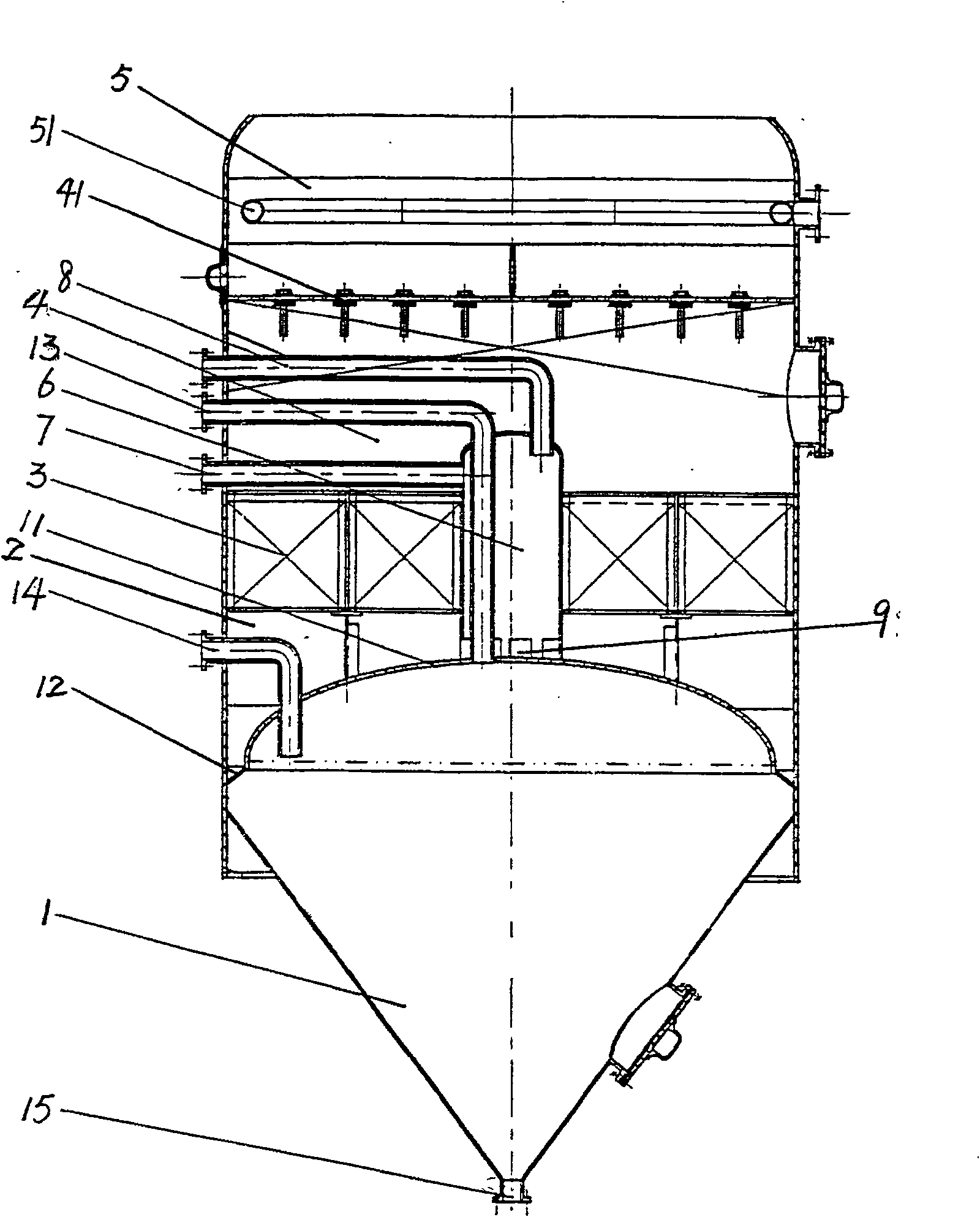
[0013] A filter, comprising a shell with an open top, and the shell is composed of a mud collecting area 1, a flocculation area 2, a sedimentation area 3, a filtering area 4, and a clean water area 5 in order from bottom to top.
[0014] The mud collecting area 1 is a conical mud collecting bucket. The top of the conical mud collecting bucket is provided with a flange cap 11. The bottom of the conical mud collecting bucket is equipped with a regular slurry discharge system 15. The conical mud collecting buckets on both sides of the flange cap 11 There is a mud water inlet 12 connected to the flocculation zone at the bucket port, an inlet pipe 13 is connected to the top of the flange cap 11, and a return pipe 14 is also arranged in the space of the conical mud collecting bucket flange cap;
[0015] The upper part of a central liquid inlet tank 6 is connected to the water inlet pipe 7, the top is connected to the exhaust pipe 8, and the bottom is fixed in the center of the flange...
PUM
Abstract
A filter, which belongs to a water purification and recovery device, includes a shell, and the shell is composed of a mud collection area, a flocculation area, a sedimentation area, a filtration area, and a clear water area in order from bottom to top. The mud collection area is a conical collection area. Mud hopper, a flange cap is placed on the top of the conical mud collecting hopper. The port of the conical mud collecting hopper on both sides of the flange cap has a mud water inlet connected to the flocculation area, and the opening on the top of the flange cap is connected to an air inlet pipe. The upper part of a central liquid inlet tank is connected to the water inlet pipe, the top is connected to the exhaust pipe, the bottom is fixed in the center of the flange cap, and there is a water outlet hole on the side wall where it connects with the flange cap. It is a multi-functional solid-liquid separation device that integrates, discharges, and cleans. It has good mud collection during operation, stable water outlet, high filter efficiency, long service life, long continuous operation time, small investment, good treatment effect, and low operating cost. It can operate continuously at low pressure, discharge the concentrated liquid regularly, and the operation and management are very convenient.
Description
technical field [0001] The invention belongs to a water purification and recovery device, in particular to a filter integrating flocculation, sedimentation and filtration. Background technique [0002] Chinese patent application 99240225.5 discloses an "integrated sedimentation, suspension, filtration and water purification device". The bottom of the device is a flocculation chamber and an air cavity, the middle is a sedimentation zone, and the upper part of the sedimentation zone is a light suspension filter material layer. The density of suspended particles is smaller than that of the filtered liquid. The upper part of the filter material is a mesh or filter cap, and the upper part of the mesh is a clean water area. The shortcomings are: 1. The sludge discharge port is set on the flat bottom surface of the shell, and the sludge in the settlement area does not have a good sludge collection device, so it is not easy to settle down, and it is easy to be mixed with coagulation...
Claims
Application Information
Patent Timeline
Application Date:The date an application was filed.
Publication Date:The date a patent or application was officially published.
First Publication Date:The earliest publication date of a patent with the same application number.
Issue Date:Publication date of the patent grant document.
PCT Entry Date:The Entry date of PCT National Phase.
Estimated Expiry Date:The statutory expiry date of a patent right according to the Patent Law, and it is the longest term of protection that the patent right can achieve without the termination of the patent right due to other reasons(Term extension factor has been taken into account ).
Invalid Date:Actual expiry date is based on effective date or publication date of legal transaction data of invalid patent.