Exhaust gas purifying apparatus, exhaust gas purifying method, and particulate matter measuring method

An exhaust purification device and a technology for particulate matter, which is applied in the field of particulate matter measurement of particulate matter, and can solve problems such as fuel efficiency reduction, engine damage, overpressure, etc.

Inactive Publication Date: 2009-10-14
IBIDEN CO LTD +1
View PDF6 Cites 0 Cited by
  • Summary
  • Abstract
  • Description
  • Claims
  • Application Information

AI Technical Summary

Problems solved by technology

If this particulate matter deposit is ignored, the exhaust can cause overpressure in the diesel particulate filter, which can lead to reduced fuel efficiency or damage to the engine

Method used


Image

  • Exhaust gas purifying apparatus, exhaust gas purifying method, and particulate matter measuring method
  • Exhaust gas purifying apparatus, exhaust gas purifying method, and particulate matter measuring method
  • Exhaust gas purifying apparatus, exhaust gas purifying method, and particulate matter measuring method

Examples


no. 1 approach

[0107] Figure 6 The configuration of the exhaust purification device according to the first embodiment of the present invention is shown.

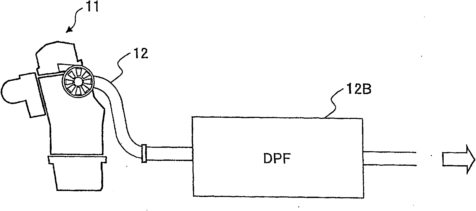
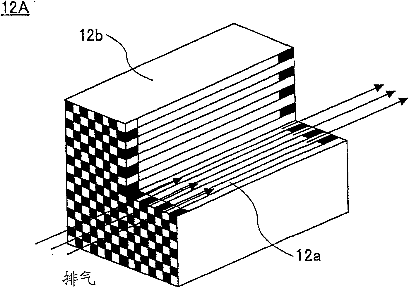
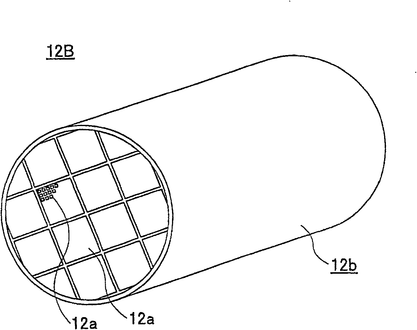
[0108] refer to Figure 6 , allowing exhaust gas from a diesel engine not shown to flow in via exhaust line 21 as previously referred to Figure 2A A similar primary diesel particulate filter (DPF) 22 as described, and as referenced Figure 2C and 2D As illustrated, a primary diesel particulate filter (DPF) 22 collects particulate matter in the exhaust.

[0109] Additionally, for Figure 6 On the upstream side of the main diesel particulate filter (DPF) 22, the auxiliary exhaust line 21A is branched from the exhaust line 21, and a volume smaller than that of the main diesel particulate filter (DPF) is set for the auxiliary exhaust line 21A. ) of the secondary diesel particulate filter 22A. In addition, a differential pressure gauge 22B is provided for measuring the differential pressure ΔP caused between the inlet and outlet of the ...

no. 2 approach

[0140] Figure 10 shows the use according to a second embodiment of the invention Figure 6 A flow chart of the exhaust purification method of the exhaust purification device.

[0141] refer to Figure 10 , in step S1, the exhaust gas flow rate Q is detected by the flow meter 24, and the differential pressure ΔP across the secondary diesel particulate filter 22A is detected by the differential pressure gauge 22B. In addition, the temperature of the exhaust gas is detected by the temperature measuring portion T1.

[0142] Next, in step S2, the layer thickness W of the particulate matter collected by the sub diesel particulate filter 22A is obtained from the differential pressure ΔP detected in step S1 according to the formula (1). It should be noted here that the temperature T of the exhaust gas can be obtained using the temperature measuring section T2 of the main diesel particulate filter (DPF) 22 instead of using the temperature measuring section T1 of the sub diesel part...


PUM


Abstract

An exhaust gas purifying apparatus comprises a primary diesel particulate filter (22) provided in an exhaust line (21) of a diesel engine, a secondary exhaust line (21A) branched from the exhaust line from an upstream side of the primary diesel particulate filter (22), a secondary diesel particulate filter (22A) provided in the secondary exhaust line (21A), the secondary diesel particulate filter (22A) having a soot storage capacity smaller than the soot storage capacity of the primary diesel particulate filter (22), and a differential pressure measuring part (22B) measuring a differential pressure between an inlet and an outlet of the secondary diesel particulate filter (22A).

Description

technical field [0001] The present invention generally relates to an exhaust gas purification device of an internal combustion engine, an exhaust gas purification method, and a particulate matter measurement method, and more particularly to a method for removing particulate matter ( PM) exhaust purification device and method thereof, and a particulate matter measurement method for particulate matter (PM) included in exhaust gas of a diesel engine. Background technique [0002] Generally, a diesel particulate filter made of porous ceramics is used to collect particulate matter mainly composed of C (carbon) emitted from a diesel engine. For this kind of diesel particulate filter, as it continues to be used, there will be a gradual deposition of particulate matter. Therefore, in the prior art of exhaust purification devices using diesel particulate filters, it is actually through the The combustion process is periodically initiated within the DPF and the DPF is regenerated to ...

Claims


Application Information

Patent Timeline
Patent Type & Authority Patents(China)
IPC IPC(8): F01N3/021F01N3/023
CPCF01N9/002F01N2560/07F01N3/027F02D2200/0812F01N2550/04F01N2560/08F01N3/0222F01N2560/06F01N13/04Y02T10/47G01N15/0618F01N2560/05F01N13/011Y02T10/40B01D53/92B01D53/02
Inventor 阿萨纳西奥斯·G·坎斯坦多普罗斯
Owner IBIDEN CO LTD
Why Eureka
Try Eureka