Device for mounting part
A technology of installation device and motion device, which is applied to electrical components, electrical components and other directions, can solve the problems of large nozzle lifting stroke, large lifting stroke of the first nozzle, and the operation of moving the nozzle downwards is not considered, etc., and saves money. Time, shorten the lifting stroke, high production efficiency
- Summary
- Abstract
- Description
- Claims
- Application Information
AI Technical Summary
Problems solved by technology
Method used
Image

Examples
Embodiment 1
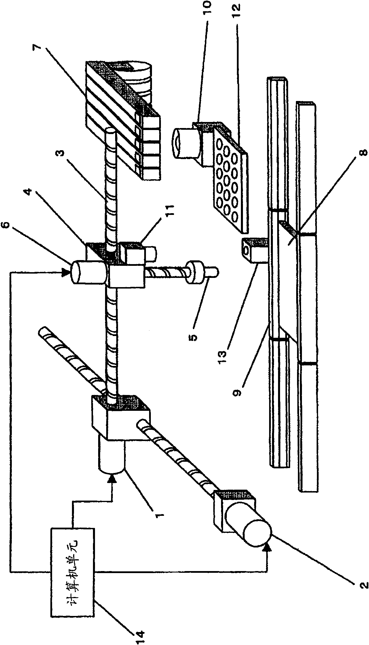
[0042] Figures 1 to 4 A component mounting device according to a first embodiment of the present invention is shown. figure 1 A component mounting device using an XY robot to mount components is shown in . An XY robot 3 (nozzle moving device) driven by an X-axis motor 1 and a Y-axis motor 2 is used. The mounting head 4 coupled to the XY robot 3 is provided movable as desired in a horizontal plane. A nozzle 5 and a Z-axis motor 6 (nozzle lifter) for moving the nozzle 5 up / down as desired are coupled to the mounting head 4 . Electronic components are housed in the component supply unit 7 .
[0043] As a method for fixing the circuit board 8, a pair of opposing transport rails 9 or the like may be employed. One cycle of the electronic component mounting operation includes a component suction operation, a component recognition operation, and a component mounting operation. In the component suction operation, the nozzle 5 moves above the component supply unit 7 and then desc...
Embodiment 2
[0064] Figure 5(a) and 5(b) A component mounting method according to a second embodiment of the present invention is shown. As shown in FIG. 5( a ), it is assumed that an obstacle 33 of a large height is located between the component camera 31 and the mounting position on the circuit board 32 . In this case, when the X-axis motor and the Y-axis motor rotate simultaneously, the nozzle passes along the path of the arrow A, thereby overcoming the obstacle 33 . On the other hand, when the nozzle passes along the path of the arrow B, the nozzle does not clear the obstacle 33 . Therefore, the nozzle can move horizontally without changing the height of the nozzle.
[0065] Fig. 5(b) shows an example of a method of controlling a nozzle path. First, the X-axis motor starts to spin. At time T1, when the X coordinate of the nozzle enters the position X1 outside the obstacle range, the Y-axis motor starts to rotate. Then, if the X-axis has not reached its target position when the Y...
Embodiment 3
[0069] A third embodiment of the present invention will be described below.
[0070] Figure 7 A schematic enlarged perspective view showing an automatic width adjustment mechanism for automatically adjusting the width between transport rails in a component mounting device.
[0071] Parts of the automatic width adjustment mechanism will be described below. The drive motor 34 that can adjust the width of the guide rail is a servo motor. The driving motor 34 with adjustable guide rail width is driven to rotate by the power supply under the control of the above-mentioned computer unit 14 to drive the lead screw 37 through a toothed belt pulley 35 and a gear belt 36 . Therefore, when the driving motor 34 of the adjustable rail width is rotated forward / backward, the movable transport rail 9b can pass through the toothed belt pulley 35, the gear belt 36, the lead screw 37 and the screw nut 38 on the right side perpendicular to the rail. - left direction forward / backward movement ...
PUM
 Abstract
Description
Claims
Application Information
 - R&D
- Intellectual Property
- Life Sciences
- Materials
- Tech Scout
- Unparalleled Data Quality
- Higher Quality Content
- 60% Fewer Hallucinations
Browse by: Latest US Patents, China's latest patents, Technical Efficacy Thesaurus, Application Domain, Technology Topic, Popular Technical Reports.
© 2025 PatSnap. All rights reserved.Legal|Privacy policy|Modern Slavery Act Transparency Statement|Sitemap|About US| Contact US: help@patsnap.com