Supercharge Your Innovation With Domain-Expert AI Agents!

Bit shank structure of gadding machine

A technology for rock drills and shank tails, which is applied in the field of improvement of shank shank structures. It can solve the problems of affecting the service life of shank tails and low fatigue resistance, and achieve the effects of improving energy utilization, reducing energy loss, and accelerating rock drilling speed.

Inactive Publication Date: 2009-10-21
东北大学钎具开发研究中心
View PDF5 Cites 0 Cited by
  • Summary
  • Abstract
  • Description
  • Claims
  • Application Information

AI Technical Summary

Problems solved by technology

Practice shows that the threaded part of the shank is the weak link, and the root of the thread is the failure part of most shanks, which seriously affects the service life of the shank
[0006] 4. Low fatigue resistance
In both cases, the bending section coefficient is very small, resulting in a large bending cycle stress σ, indicating that bending fatigue is carried under a high level of σ stress state, which will seriously affect the service life of the shank

Method used


Image

  • Bit shank structure of gadding machine
  • Bit shank structure of gadding machine
  • Bit shank structure of gadding machine

Examples


Embodiment Construction

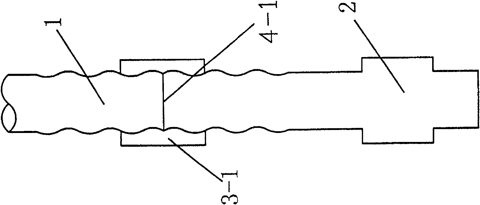
[0029] In Fig. 1, 1 is a drill rod, 2 is a drill tail, 3-1 is a casing, and 4-1 is a bearing surface. Structural features of the present invention are as follows:

[0030] 1. Do not change the internal structure of the rock drill, retain the type of screw shank tail, and use the empty slit end face at the root of the male thread as the position for transmitting the stress wave bearing surface, such as image 3, Figure 4 Show.

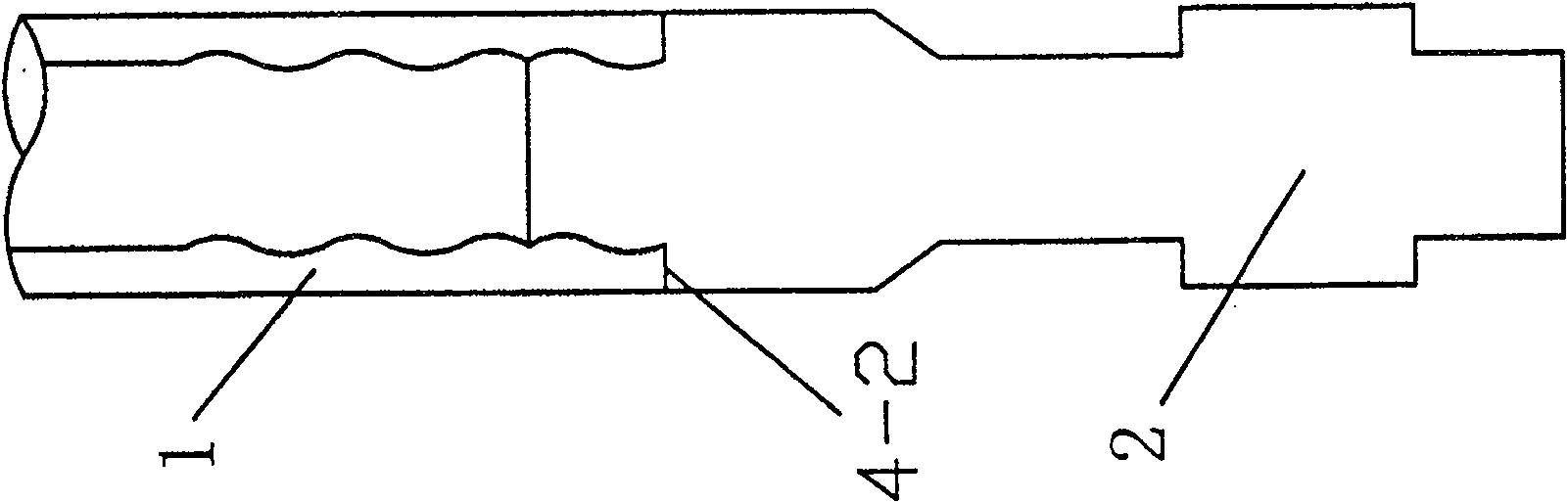
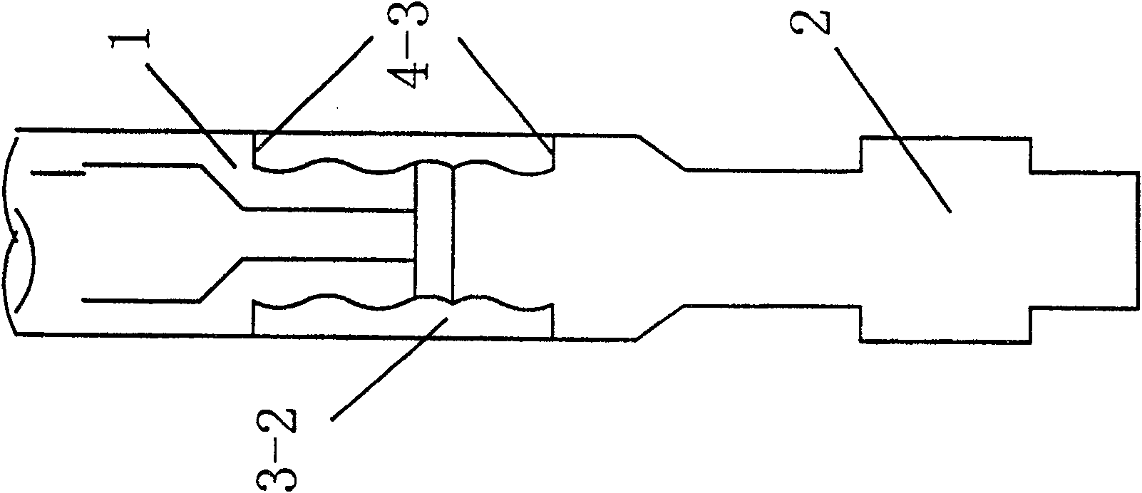
[0031] 2. The screw type shank 2 and the rock drilling tubular drill rod 1 are connected through the double bridge nut bushing 3-2, and the bearing surface for transmitting the rock drilling stress wave is designed on the two end faces 4 of the double bridge nut bushing -3, as in Figure 3 shown. 3-2 is the double bridge nut bushing among Fig. 3. When the thread diameter or thread type of the rock drilling tubular drill rod and the screw shank are different, the half-bridge nut sleeve connection will be used between the two, such as Figure 4 sho...


PUM


Abstract

The invention discloses a shank tail structure of a rock drilling machine. The shank has a screw or nut structure; increase the shaft diameter from the rotating tooth to the threaded section of the shank to ensure that the non-threaded size of the shank root is larger than the thread diameter; the male thread root of the screw shank has an empty sip The end face of the shank or the outer end plane of the female thread of the nut type shank is the stress wave bearing surface, and the end face of the male thread or the bottom plane of the nut hole is the suspended surface, that is, the free surface. By changing the position of the stress wave bearing surface, the invention can ensure that the rock drilling energy is distributed along the peripheral column at the output end of the shank shank, avoid oblique incidence of the wave during the stress wave transmission process, and reduce energy loss during the transmission process. The invention can ensure that the wet bending fatigue stress circulates at a low amplitude, and can greatly improve the anti-fatigue ability of the shank. The invention has the advantages of high energy utilization rate, fast rock drilling speed, high anti-fatigue ability of the shank, significantly increased service life and the like.

Description

technical field [0001] The invention relates to an improvement technology of a heavy-duty pneumatic rock drill and various hydraulic rock drills, in particular to an improvement technology of a shank structure for outputting impact force and torque of the rock drill and transferring energy. Background technique [0002] The heavy-duty percussion rock drill includes the inside of the pneumatic rock drill and hydraulic rock drill, and transmits the impact force of the rock drill piston and the torque of the rotary drill structure according to its shank parts. There are two types of shank shanks for various rock drills: one is a screw-type shank with a male thread at the output end; the other is a nut-type shank with a female thread at the output (Hong Daling, Gu Taihe, etc. Edited, Brazing Steel and Brazing Tools, Metallurgical Industry Press, September 2000, P24~369). ). [0003] 1. The bearing surface of the two kinds of rock drilling shanks that transmit the rock drilling...

Claims


Application Information

Patent Timeline
Patent Type & Authority Patents(China)
IPC IPC(8): E21B10/02
Inventor 宋守志张国联邢军唐春安邱景平钟勇徐小荷
Owner 东北大学钎具开发研究中心
Features
  • R&D
  • Intellectual Property
  • Life Sciences
  • Materials
  • Tech Scout
  • Unparalleled Data Quality
  • Higher Quality Content
  • 60% Fewer Hallucinations
Learn More