Exhaust gas purification device for internal combustion engine

An exhaust gas purification device and internal combustion engine technology, which is applied in the direction of exhaust devices, internal combustion piston engines, noise reduction devices, etc., can solve the problems of catalyst performance deviation, time-consuming, and easy deterioration, and achieve reliable purification, easy installation, and improved utilization efficiency. Effect

Inactive Publication Date: 2009-10-28
KOMATSU LTD
View PDF6 Cites 1 Cited by
  • Summary
  • Abstract
  • Description
  • Claims
  • Application Information

AI Technical Summary

Problems solved by technology

[0009] However, in the exhaust gas purifying device described in Patent Document 1, since the DeNOx catalyst is arranged around the DPF and the entire body is covered with a can, in order to reverse the DPF, it is necessary to pull out the DEF surrounded by the DeNOx catalyst after opening the can. , then reverse and insert again, thus taking time, very cumbersome
[0010] In addition, since the DeNOx catalyst is always fixed in the same direction, the closer to the inflow side of the exhaust gas, the easier it is to deteriorate, and the performance of the catalyst varies between the inflow side and the outflow side, resulting in a problem that the utilization efficiency of the DeNOx catalyst is poor.

Method used


Image

  • Exhaust gas purification device for internal combustion engine
  • Exhaust gas purification device for internal combustion engine
  • Exhaust gas purification device for internal combustion engine

Examples


no. 1 approach

[0064] A first embodiment of the present invention will be described below with reference to the drawings.

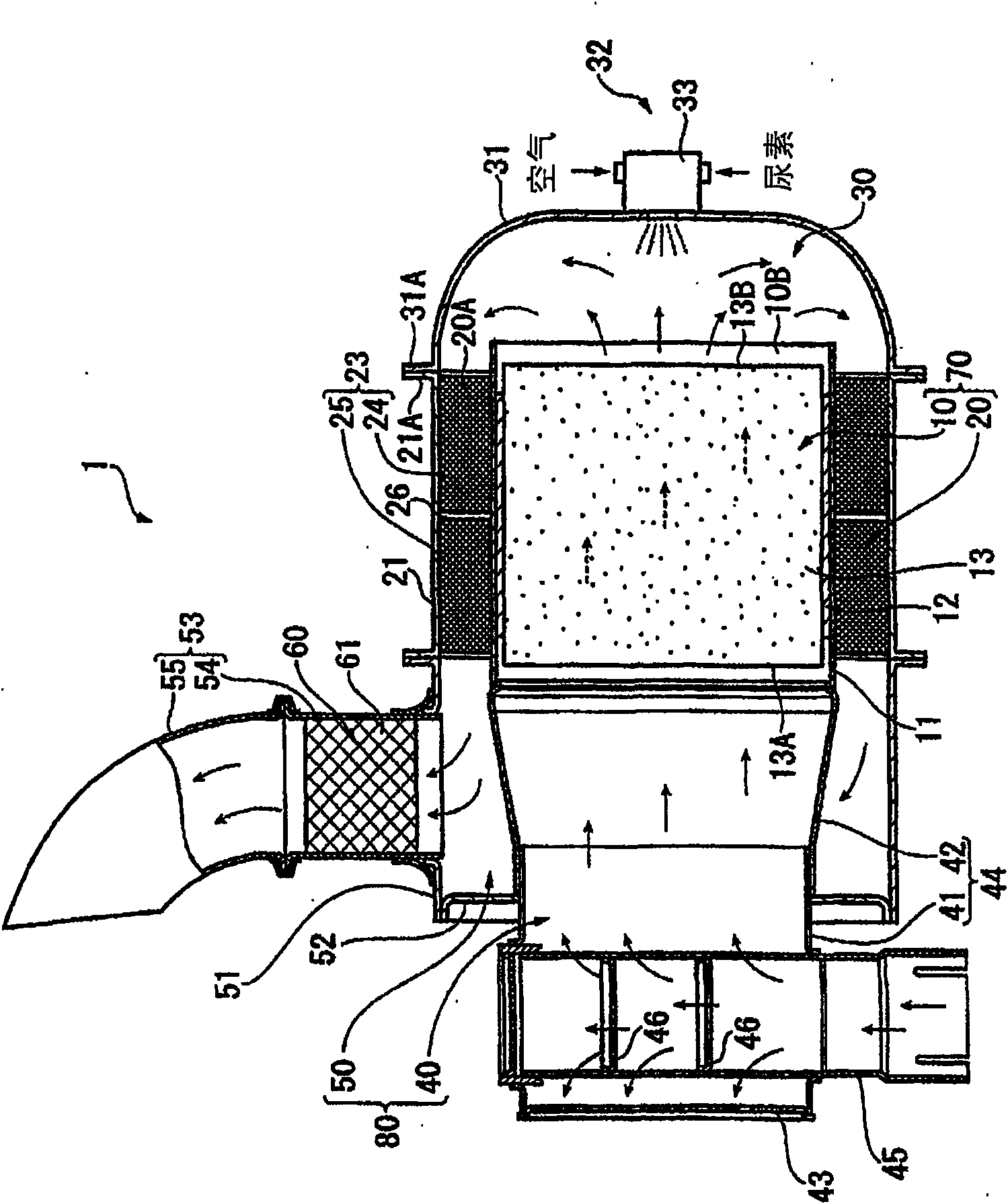
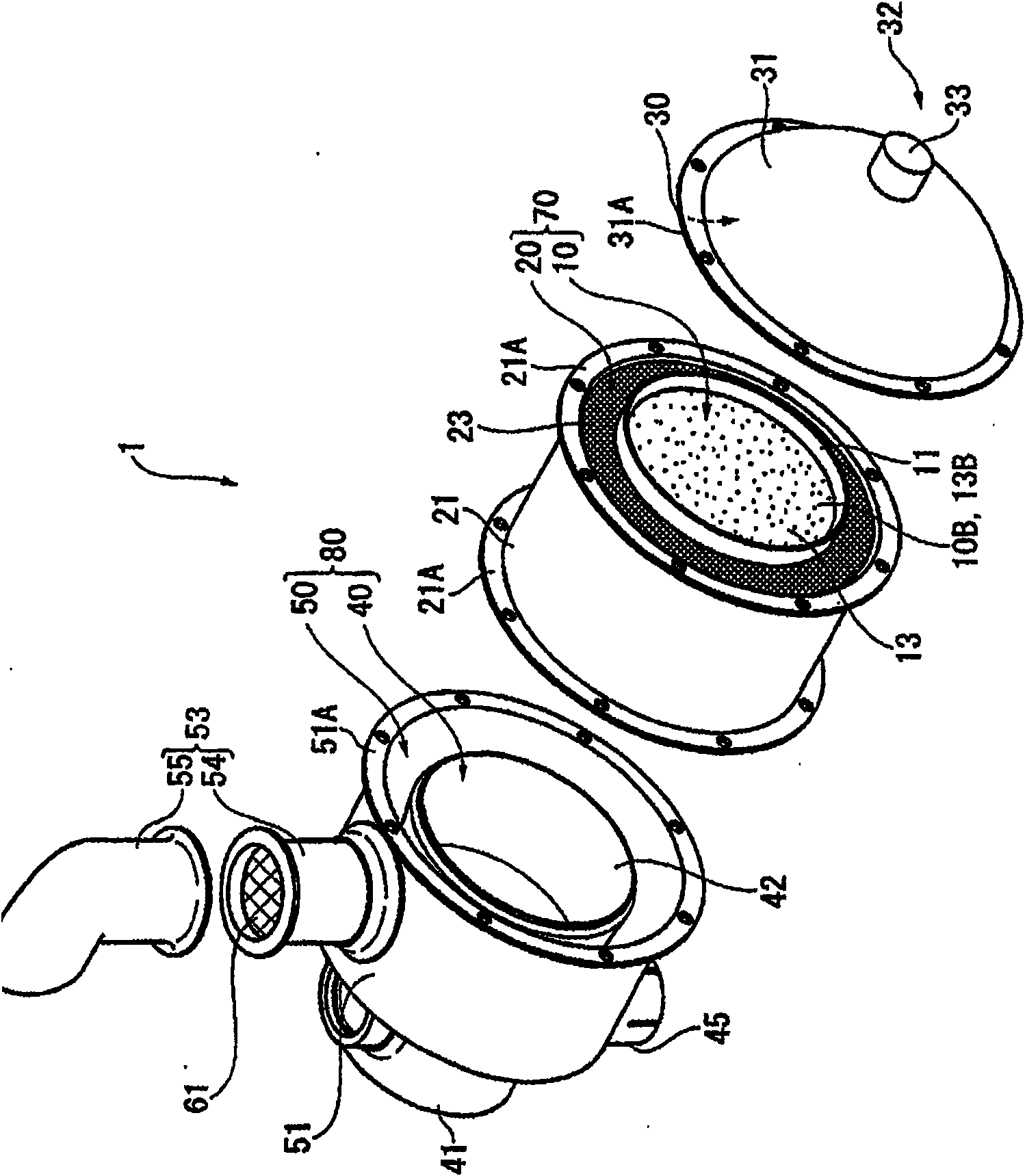
[0065] figure 1 It is a sectional view showing the whole of the exhaust gas purification device 1 for an internal combustion engine according to this embodiment, figure 2 is its exploded perspective view. In addition, a diesel engine is mainly assumed as the internal combustion engine of this embodiment.

[0066] The exhaust gas purification device 1 is installed in the exhaust flow path of the diesel engine, which is a device for trapping particulates contained in the exhaust gas and reducing the emission amount of NOx discharged into the atmosphere, and the exhaust gas purification device 1 also serves as an exhaust gas silencer. Moreover, this exhaust gas purification device 1 is suitable for installation in construction machines such as hydraulic excavators, bulldozers, and wheel loaders.

[0067] Such as figure 1 and figure 2 As shown, the exhaust gas purif...

no. 2 approach

[0108] Next, a second embodiment will be described. In the following description, the same reference numerals are assigned to the same parts as those already described, and the description thereof will be omitted.

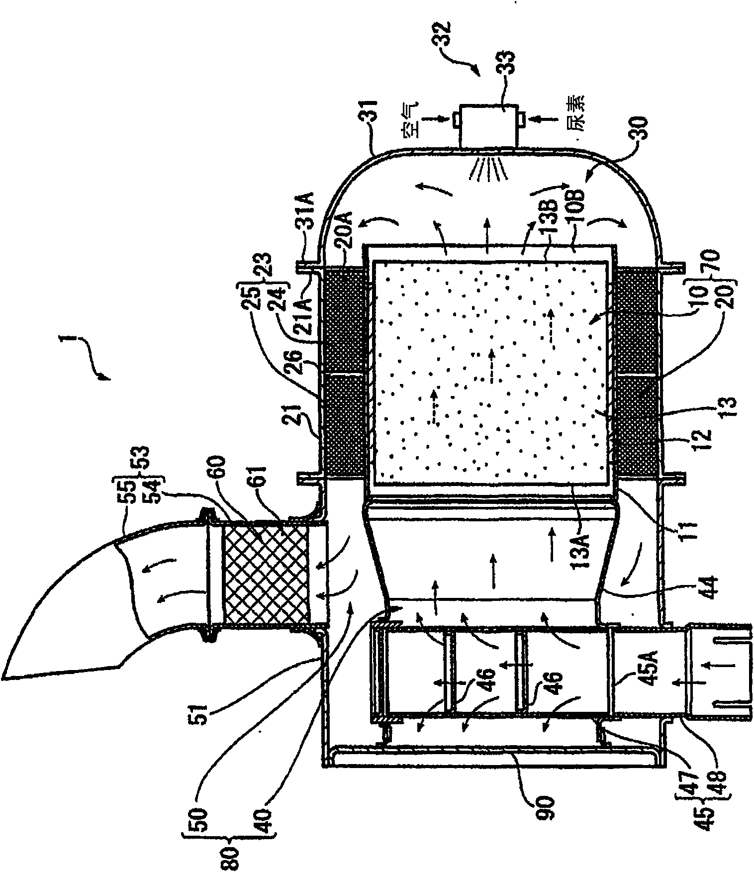
[0109] As a second embodiment of the present invention, image 3 A further embodiment of the inlet chamber 40 and the outlet chamber 50 of the exhaust gas purification device 1 is shown.

[0110] In the present embodiment, one end side of the inlet chamber 40 and the outlet chamber 50 is closed by a common side wall portion 90 . However, it is of course also possible to provide the side wall portion separately.

[0111] Furthermore, by arranging the entire inner cylinder 44 inside the outer cylinder 51 , the inlet chamber 40 is completely covered by the outlet chamber 50 , and the inlet pipe 45 provided on the inlet chamber 40 penetrates the peripheral wall of the outer cylinder 51 . In addition, the inlet chamber 40 is downsized to the extent that it can be acc...


PUM


Abstract

An inlet chamber 40 and outlet chamber 50 for exhaust gas are integrated as an inflow / outflow section 80, and a first post treatment device 10 equipped with a DPF 13 at its central portion and second post-treatment device 20 equipped with a urea DeNOx catalyst 23 on its outer periphery side are integrated as a catalyst installation section 70. The catalyst installation section 70, the inflow / outflow section 80, and a communication chamber forming section 30 are provided separately and detachably from one another, and the catalyst installation section 70 is made installable in a reversible manner. As a result, by reversing the catalyst installation section 70, it is possible to easily reverse the DPF 13 without having to extract it from the central part. Further, since the urea DeNOx catalyst 23 is reversed simultaneously, it is possible to change the direction in which the exhaust gas flows therein, thereby enabling to prevent unbalanced deterioration of the urea DeNOx catalyst 23.

Description

technical field [0001] The present invention relates to an exhaust gas purification device of an internal combustion engine, and in detail, relates to an exhaust gas purification device of an internal combustion engine for purifying exhaust gas provided in an exhaust flow path of the internal combustion engine. Background technique [0002] Conventionally, it is known to install an exhaust gas purification device in an exhaust flow path of an internal combustion engine in order to trap particulates (particulate matter) in exhaust gas discharged from an internal combustion engine such as a diesel engine or to reduce the amount of NOx. [0003] As an exhaust gas purification device for trapping particulates, a device equipped with a diesel particulate filter (hereinafter referred to as DPF (Diesel Particulate Filter)) was developed, and as an exhaust gas purification device for reducing the amount of NOx, a device equipped with a NOx reduction Catalysts, NOx absorption and red...

Claims


Application Information

Patent Timeline
Patent Type & Authority Patents(China)
IPC IPC(8): F01N3/28F01N3/08B01D53/86F01N3/24B01D53/94B01D46/42F01N3/02
CPCF01N2610/03F01N2490/06B01D53/9431B01D53/944F01N2013/026F01N3/106B01D2251/2067F01N2470/18F01N3/0233F01N3/36F01N2250/02F01N2610/1453F01N3/035Y02T10/24F01N2450/30F01N3/105F01N3/2066F01N2610/02F01N13/0097Y02T10/12B01D46/42B01D53/86B01D53/94F01N3/02F01N3/0814F01N3/2803B01D53/34F01N3/20F01N3/28
Inventor 西山利彦饭岛浩二
Owner KOMATSU LTD
Why Eureka
Try Eureka