Adjustable elastic support structure
An elastic support and adjustable technology, applied in the direction of the casing/cover/support, electrical components, electromechanical devices, etc., to achieve the effect of reducing additional force, simple structure, and reducing transmission
- Summary
- Abstract
- Description
- Claims
- Application Information
AI Technical Summary
Problems solved by technology
Method used
Image
Examples
Embodiment 1
[0015] Embodiment 1: Take the single fulcrum adjustable support as an example.
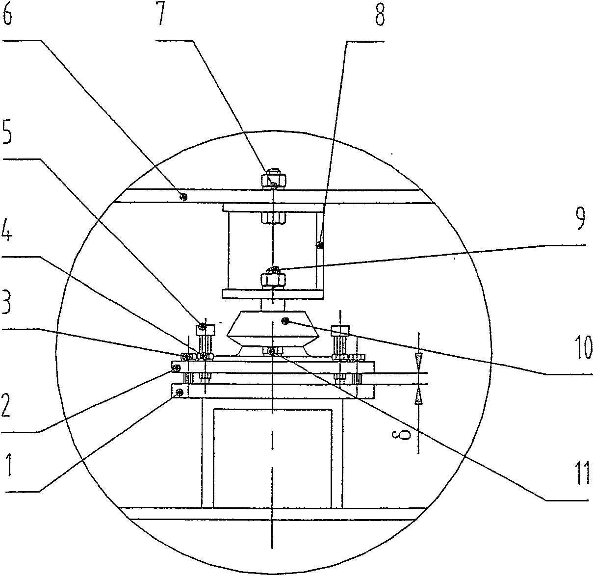
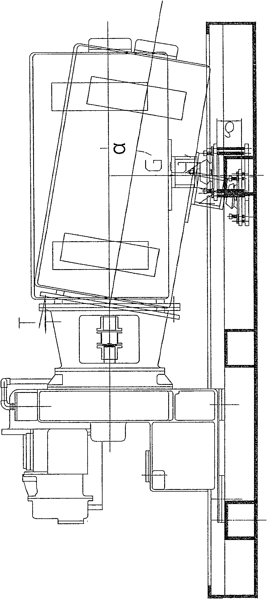
[0016] like figure 1 Shown: The gearbox side is supported by a shock absorber, which can be considered rigid, and all deviations are balanced by the motor support. The weight of the motor is G, and the motor has a vertical downward force G on the frame. In theory, the frame has a vertical upward support force N, which is used to balance the weight of the motor. At this time, it can be considered that the additional force of the connecting bolts on the connecting cylinder due to various errors and deformations is zero.
[0017] When considering the influence of various errors, the bracket is lower than the original δ, which causes the center line of the motor to deviate from the theory by an angle of α. At this time, the connecting bolts on the connecting cylinder will be subjected to an additional force T due to the error. At this time by adjusting figure 1 The top screw 5 in the middle makes t...
Embodiment 2
[0018] Embodiment 2: It is a connection and installation diagram of a typical screw compressor.
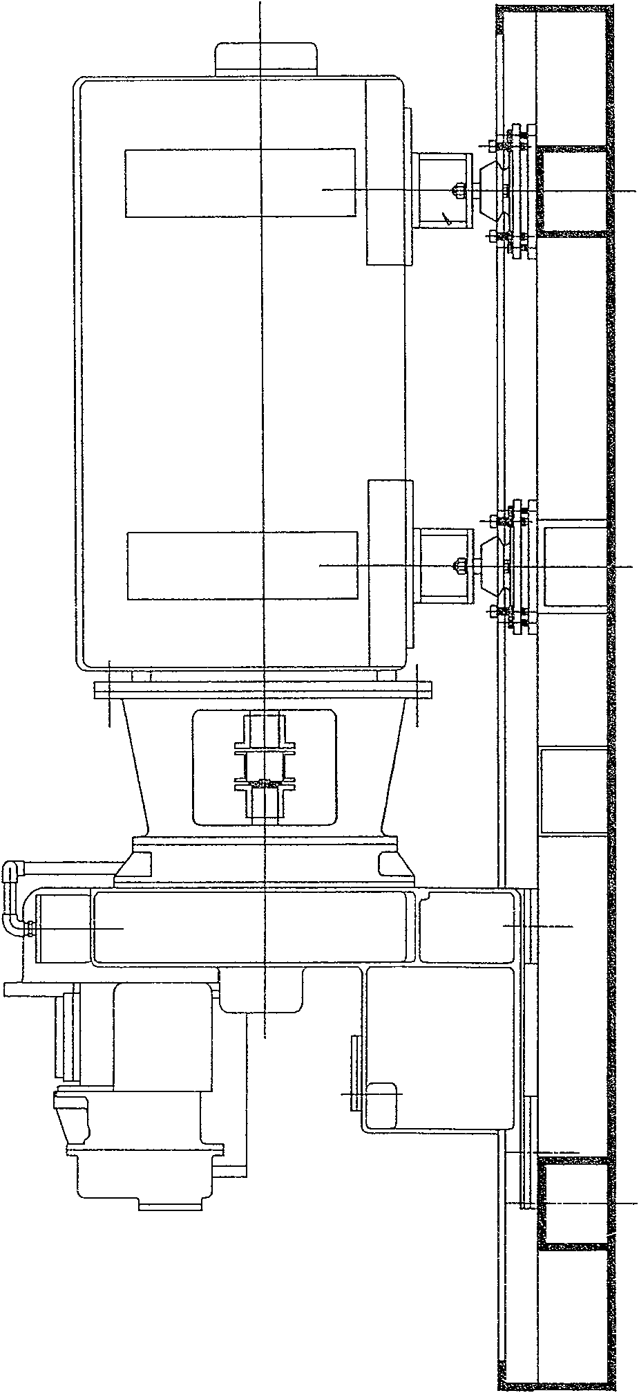
[0019] like image 3 As shown: the compressor is hung on the transmission gearbox, and the motor is connected with the transmission gearbox through the connecting cylinder and coupling. They sit on the base as a rigid whole, with shock-absorbing pads and shock absorbers (adjustable elastic supports) in the middle.
[0020] The comprehensive errors of the manufacture and installation of each component are relatively large, including: the center height error, the verticality error of the connecting surface of the motor and the gearbox, etc. The comprehensive error can reach more than 10mm, and the whole unit is supported by multiple fulcrums (for example, 8 points), resulting in The force of each support point is seriously uneven (far from the ideal force), and at the same time, the connecting cylinder is subjected to a large additional bending moment, which causes vibration and no...
PUM
 Abstract
Description
Claims
Application Information
 - R&D
- Intellectual Property
- Life Sciences
- Materials
- Tech Scout
- Unparalleled Data Quality
- Higher Quality Content
- 60% Fewer Hallucinations
Browse by: Latest US Patents, China's latest patents, Technical Efficacy Thesaurus, Application Domain, Technology Topic, Popular Technical Reports.
© 2025 PatSnap. All rights reserved.Legal|Privacy policy|Modern Slavery Act Transparency Statement|Sitemap|About US| Contact US: help@patsnap.com


