
Method for switching service in optical virtual special network and optical network system

An optical virtual private network and service technology, applied in the field of optical network, can solve the problems affecting network service quality, service interruption, high price, etc., to improve service stability and network service quality, avoid service interruption, save money The effect of networking cost

Inactive Publication Date: 2009-11-04
HUAWEI TECH CO LTD
View PDF5 Cites 1 Cited by
  • Summary
  • Abstract
  • Description
  • Claims
  • Application Information

AI Technical Summary

Problems solved by technology

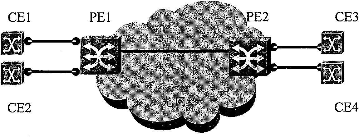
[0006] In the existing OVPN system, the port connected to the CE on the PE can be the optical port of the WDM device or the optical port of the data board of the Synchronous Digital Hierarchy (SDH) device, which is expensive, and because each PE needs to occupy There are many ports, so the networking cost of OVPN is relatively high
In addition, for optical network equipment, if the two working time periods before and after the switchover occur, the services of different CEs will not change in the operator's network, although the communication bandwidth and path are in the two time periods of T1 and T2 None have changed, but operators have to adjust network routing due to service switching
The reconfiguration of the cross-connect in the process of adjusting the routing will lead to the instantaneous interruption of the business, thus affecting the quality of network service

Method used


Image

  • Method for switching service in optical virtual special network and optical network system
  • Method for switching service in optical virtual special network and optical network system
  • Method for switching service in optical virtual special network and optical network system

Examples


Embodiment 1

[0057] Figure 4 Taking two optical switches as an example, a schematic structural diagram of the OVPN system in this embodiment is shown. see Figure 4 , the OVPN system in this embodiment includes a VPN manager and a service time distribution database in addition to PEs and optical switches as switching devices. Among them, the business time distribution database is used to save the CE in the complementary business and the corresponding working time period, and the VPN manager is used to read data from the business time distribution database, determine the switching time point according to the read data, and switch At the time point, the optical switch corresponding to the CE that has completed the work is notified to release the CE and / or the information of the CE that needs to be connected in the next working period is notified to the optical switch corresponding to the CE, so that the optical switch performs the communication between the CE and the PE. connectivity. Th...

Embodiment 2

[0071] Figure 6 Taking two optical switches as an example, a schematic structural diagram of the OVPN system in this embodiment is shown. see Figure 6 , in the OVPN system in this embodiment, the CE and the corresponding working time period of each service in the complementary business related to itself are saved in the PE, and the boundary value of the working time period is determined according to the working time period saved by itself It is its own switching time point. When the switching time point is reached, the PE corresponding to the switching time point notifies the optical switch connected to the PE to release the CE that has completed the work and / or informs the optical switch that there will be a communication demand in the next working time period. The CE connected to the corresponding PE.

[0072] Figure 7 A flow chart of the OVPN service switching method in this embodiment is shown. Assuming that the CEs and working hours involved in each service in this...

Embodiment 3

[0083] Figure 8 Taking three optical fiber crossover matrices as an example, the structure diagram of the OVPN system in this embodiment is shown. see Figure 8 , the OVPN system in this embodiment is similar to that in Embodiment 1, except for the PE and the fiber optic crossover matrix as switching equipment, it also includes a VPN manager and a service time distribution database. Among them, the service time distribution database is used to save the CE in the complementary service and the corresponding working time period, and the VPN manager is used to read data from the service distribution time database, determine the switching time point according to the read data, and switch At the time point, notify the fiber cross matrix corresponding to the CE that has completed the work to release the CE and / or notify the fiber cross matrix corresponding to the CE that needs to be connected in the next working period, so that the fiber cross matrix executes the CE and Connectivi...


PUM


Abstract

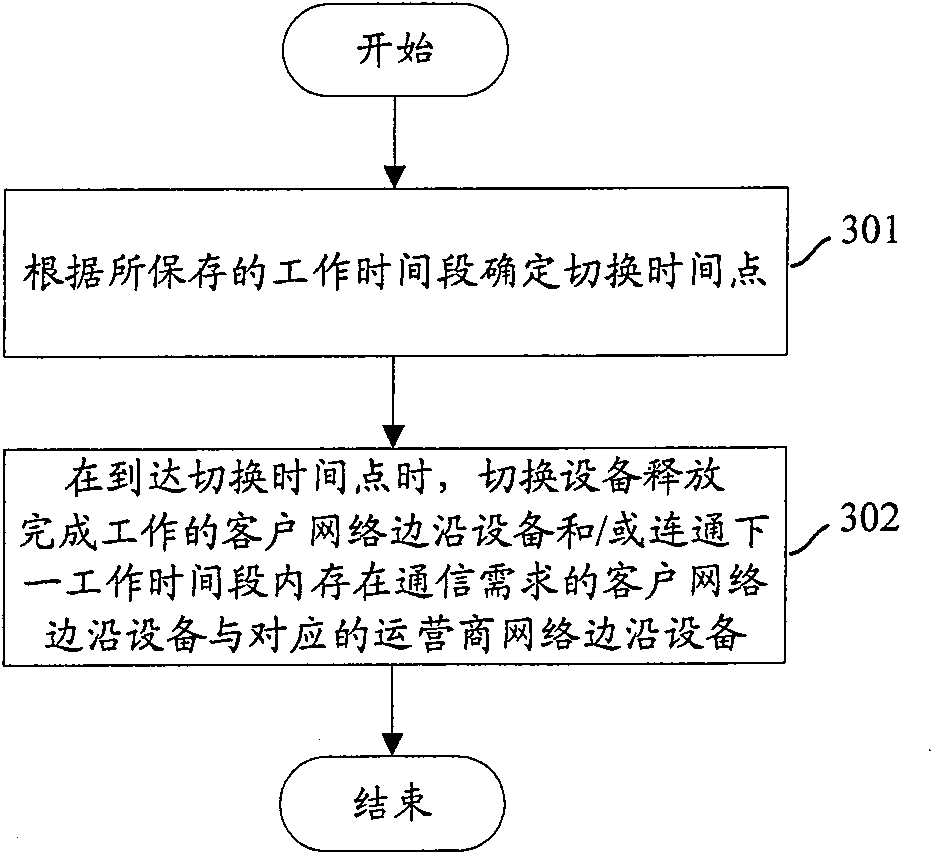
The system comprises: PE and switch device located between PE and CE. Said PE is used for providing OVPN network access for CE; said switch device is used for releasing the CE completing work and / or connecting the PE to the CE used for word in next time interval at a switch time point. The invention also reveals a method of switching OVPB service, which comprises: presetting up a switch device between PE and CE, and pre-saving the working time interval corresponding to the CE; according to the saved time interval, determining a switch time point; b) when reaching the switch time point, the switch device releases the CE completing the work and / or connecting the CE to its corresponding PE in next work time interval, according to the saved working time interval corresponding to the CE. The invention can reduce the occupation of the port on PE.

Description

technical field [0001] The invention relates to optical network technology, in particular to a service switching method and an optical network system in an optical virtual private network (OVPN). Background technique [0002] OVPN is a new service application that appears during the transition from optical network to Automatically Switched Optical Network (ASON). )business. Such an OVPN is usually called a Layer 1 VPN (L1VPN). [0003] OVPN enables operators to divide their optical network into multiple blocks for multiple end users, and provides comprehensive and secure viewing and management of users' own OVPN capabilities, as if each user has their own optical network, making Users can flexibly build their own network topology within the public network while reducing communication costs. By owning OVPN, operators can optimize bandwidth utilization and provide more flexible and multifunctional wavelength services that are different from ordinary bandwidth services in th...

Claims


Application Information

Patent Timeline
Patent Type & Authority Patents(China)
IPC IPC(8): H04L12/46H04Q11/00
CPCH04Q11/0071H04Q11/0062H04Q11/0067H04Q2011/0084H04Q2011/0088
Inventor 易其亮
Owner HUAWEI TECH CO LTD
Learn More