
Conical parallel dual-screw extruding machine

A conical twin-screw and conical screw technology, applied in the field of conical twin-screw extruders, can solve the problems of small extrusion force, poor plasticizing performance, affecting product quality, etc., to maintain plasticizing performance and ensure plastic The effect of improving the quality and increasing the mixing performance

Inactive Publication Date: 2009-12-02
吴汉民 +1
View PDF1 Cites 4 Cited by
  • Summary
  • Abstract
  • Description
  • Claims
  • Application Information

AI Technical Summary

Problems solved by technology

[0002] As we all know, the extruders currently used in plastic or rubber processing include parallel co-rotating twin-screw extruders, parallel counter-rotating twin-screw extruders and conical counter-rotating twin-screw extruders; parallel co-rotating twin-screw extruders The advantage of the extruder is that it has good plasticizing performance, but its disadvantages are that the extrusion force is small, the structure of the deceleration distribution box is complicated, and the power consumption is large; while the parallel counter-rotating twin-screw extruder is not good in plasticizing performance and extrusion force; and The advantage of the conical counter-rotating twin-screw extruder is that the extrusion force is large, and the disadvantage is that the plasticizing performance is poor, so it is not satisfactory in actual use. It seems that the plasticizing performance and the extrusion force in the extruder become the same Contradiction
We know that poor plasticizing performance will directly affect the quality of the plasticized product, and the extrusion force will affect the output and cost. Therefore, can we design an extruder that integrates the above advantages and eliminates its disadvantages? , to break through the defects of the current extruder and update the processing capacity of the equipment, it seems to have very important economic value and application value

Method used


Image

  • Conical parallel dual-screw extruding machine
  • Conical parallel dual-screw extruding machine
  • Conical parallel dual-screw extruding machine

Examples


Embodiment Construction

[0011] specific implementation

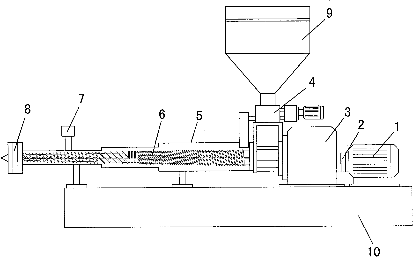
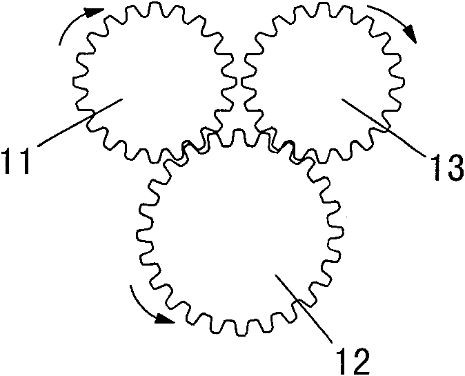
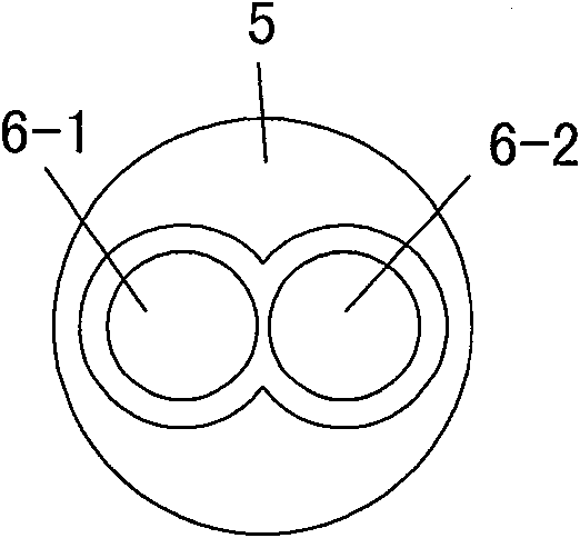
[0012] The structure of the present invention is attached figure 1 As shown, it consists of drive motor 1, coupling 2, deceleration distribution box 3, feeding system 4, barrel 5, conical twin screw 6, exhaust system 7, extrusion pelletizing system 8, hopper 9 and machine The structure of the present invention is that the screw 6 is composed of two conical screws 6-1 and 6-2, the conical screw 6-1 is the main screw, and the conical screw 6-2 is the auxiliary screw. Figure 4 shown, their position in the barrel 5 is shown in the appendix image 3 shown; in the reduction distribution box 3, three bevel gears are arranged, see appendix figure 2 As shown, the drive motor 1 is connected with the driving gear 11 through the coupling 2, the driving gear 11 is meshed with the intermediate gear 12, the intermediate gear 12 is meshed with the driven gear 13; the driving gear 11 is meshed with the main conical screw 6-1 Connected, the driven gear 13 i...


PUM


Abstract

The invention discloses a conical co-rotating twin-screw extruder, which consists of a drive motor (1), a coupling (2), a deceleration distribution box (3), a feeding system (4), and a barrel (5) , conical twin-screw (6), exhaust system (7), pelletizing system (8), hopper (9), etc., and there are two main conical screws rotating in the same direction in the barrel (5) (6-1) and secondary conical screw (6-2), which are respectively connected with the driving gear (11) and the driven gear (13) in the deceleration distribution box (3), there is also a gear below the second gear Intermediate gear (12), so that the conical twin-screws keep rotating in the same direction during work, and the helixes of the conical twin-screws also rotate in the same direction; this will improve the plasticizing performance of the present invention, and the good extrusion performance, so that the present invention has both good extrusion force and good plasticity, suitable for extrusion and granulation in plastic processing, which improves output and reduces energy consumption. It is suitable for various plastics and rubber processing. new extruder.

Description

technical field [0001] The invention discloses a conical twin-screw extruder suitable for extrusion and granulation used in plastic or rubber processing. Background technique [0002] As we all know, the extruders currently used in plastic or rubber processing include parallel co-rotating twin-screw extruders, parallel counter-rotating twin-screw extruders and conical counter-rotating twin-screw extruders; parallel co-rotating twin-screw extruders The advantage of the extruder is that it has good plasticizing performance, but its disadvantage is that the extrusion force is small, the structure of the deceleration distribution box is complex and the power consumption is large; while the parallel counter-rotating twin-screw extruder is not good in plasticizing performance and extrusion force; The advantage of the conical counter-rotating twin-screw extruder is that the extrusion force is large, and the disadvantage is that the plasticizing performance is poor, so it is not sat...

Claims


Application Information

Patent Timeline
Patent Type & Authority Patents(China)
IPC IPC(8): B29C47/40B29C48/535B29C48/40B29C48/405
CPCB29C47/6025B29C48/535B29C48/405B29C48/40
Inventor 吴汉民
Owner 吴汉民
Learn More