
Reprocessing method for maximum-density projection image data

A technology of maximum density and projected image, applied in the field of image processing, it can solve the problems of deformation and blurred details of 3D image tissue texture, and achieve the effect of realistic 3D projection image, clear tissue texture details, and no deformation.

Active Publication Date: 2009-12-02
LANWON TECH
View PDF3 Cites 0 Cited by
  • Summary
  • Abstract
  • Description
  • Claims
  • Application Information

AI Technical Summary

Problems solved by technology

[0003] The technical problem to be solved by the present invention is to provide a post-processing method of maximum density projection image data, which overcomes the defects of blurred or even deformed tissue texture details of three-dimensional images obtained by post-interpolation methods in the prior art

Method used


Image

  • Reprocessing method for maximum-density projection image data
  • Reprocessing method for maximum-density projection image data
  • Reprocessing method for maximum-density projection image data

Examples


Embodiment Construction

[0039] Below according to accompanying drawing and embodiment the present invention will be described in further detail:

[0040] 1. Record the offset of adjacent slice layers on the projection plane

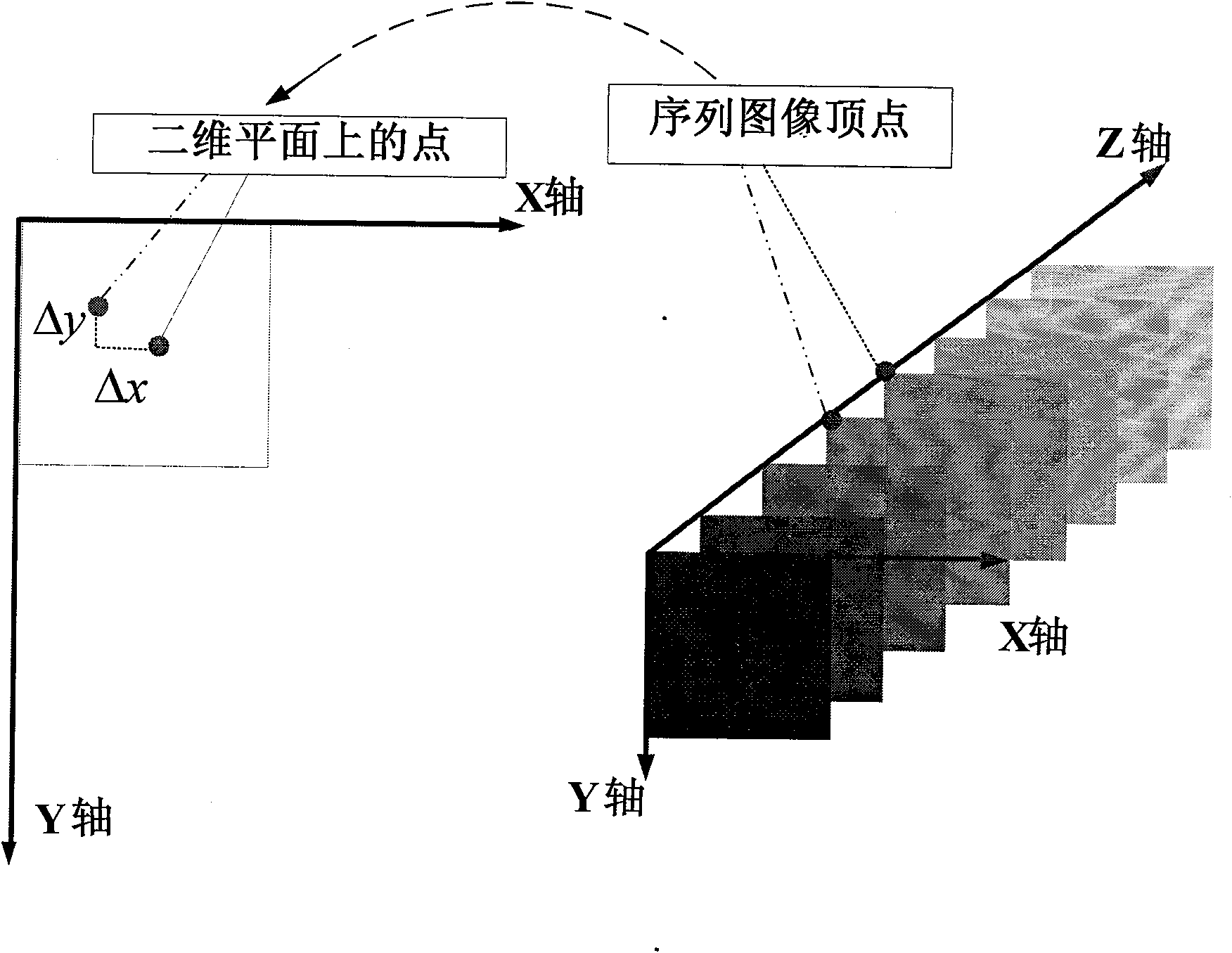
[0041] Such as figure 1 As shown, assuming that there are a total of N in the image sequence 1 images, denoted as Q 1 , Q 2 ,...,Q N , the vertices of each image sequence correspond to the points on the two-dimensional plane and are recorded as P 1 , P 2 ,...,P N . In a two-dimensional plane, from these points one can obtain P 2 relative to P 1 The offset (Δx 1 , Δy 1 ), P 3 relative to P 2 (Δx 2 , Δy 2 ),...., until P N relative to P N-1 The offset (Δx N-1 , Δy N-1 ).

[0042] 2. Process the MIP image

[0043] There are many methods for performing maximum density projection on image sequences in the prior art. Since the present invention performs post-processing on the data obtained after maximum density projection, it is not limited to a specific maximum d...


PUM


Abstract

The invention discloses a post-processing method for the image data of the maximum intensity projection, comprising the following steps of: A1 before the maximum intensity projection of an image sequence, selecting a vertex at the same position of each image, making a calculation in accordance with an ascending order or a descending order of the image sequence, and keeping records for coordinating deviation of vertexes of the adjacent two images on the projection plane; A2 after the maximum intensity projection of the image sequence, recording the coordinates and gray values of each pixel in the projection data, the marks of the image where the pixels are arranged and the relations between the pixels and the image, and conducting a post-processing for the pixels.

Description

technical field [0001] The invention relates to the technical field of image processing, in particular to a post-processing method for maximum density projection image data. Background technique [0002] In image processing technology, the establishment of a three-dimensional image can be completed by projecting a two-dimensional image sequence. Maximum intensity projection (MIP, Maximum intensity projection) ), (computed tomography, computerized tomography) data volume to obtain an effective image reconstruction method for three-dimensional structures such as blood vessels, bones and soft tissues. In order to use computers to quickly process images and meet the time requirements for image reconstruction, people have researched and developed a lot of maximum intensity projection MIP algorithms. data, these image data cannot fully satisfy the Nyquist sampling law, so it is impossible to completely reproduce the original appearance of the three-dimensional object after the ma...

Claims


Application Information

Patent Timeline
Patent Type & Authority Patents(China)
IPC IPC(8): G06T11/00G06T15/00G06T15/04
Inventor 陈闽峰吕广志
Owner LANWON TECH
Learn More