Supercharge Your Innovation With Domain-Expert AI Agents!

Transformer structure

A technology of transformers and circuit units, applied in the direction of transformers, fixed transformers, transformer/inductor coils/windings/connections, etc., to reduce losses and improve efficiency

Active Publication Date: 2009-12-16
DELTA ELECTRONICS INC
View PDF3 Cites 3 Cited by
  • Summary
  • Abstract
  • Description
  • Claims
  • Application Information

AI Technical Summary

Problems solved by technology

Therefore, based on the shortcomings of the above-mentioned prior art and the many adverse effects of traditional transformers, the present invention provides a transformer structure that can effectively reduce the length of the AC lead and the loss of the transformer so as to improve the efficiency of the overall circuit

Method used


Image

  • Transformer structure
  • Transformer structure
  • Transformer structure

Examples


Embodiment Construction

[0054]Embodiments of the present invention are described in detail as follows in conjunction with the accompanying drawings.

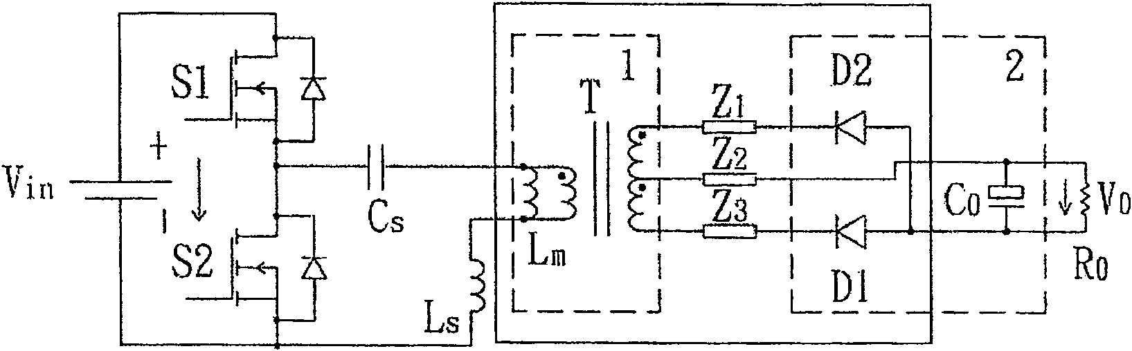
[0055] Please refer to the drawings, which are only for illustrating preferred embodiments of the present invention, and are not intended to limit the present invention. Such as image 3 Shown is the block diagram of the LLC series resonant circuit of the half bridge, which illustrates the transformer secondary side complex output rectifier unit (including the output filter capacitor). The transformer structure of the present invention can be applied to high-power transformers, and is not limited to high-power transformers, and can also be applied to transformers of other powers. Generally speaking, the inductor (Ls), capacitor (Cs) and the magnetizing inductance (Lm) of the transformer form an LLC resonant circuit. The two main switches S1 and S2 form a half-bridge structure, and the constant output voltage is realized by changing the switching freq...


PUM


Abstract

The present invention provides a transformer structure, comprising: a primary coil; a plurality of secondary circuit units, each of which includes a printed circuit board composite; the printed circuit board composite includes at least one A printed circuit board of the secondary conductor coil; and at least one output rectifying circuit, disposed on the printed circuit board complex, wherein the output rectifying circuit includes an output filter device and a rectifying device. The invention can effectively reduce the length of the AC leads and the loss of the transformer, thereby improving the efficiency of the whole circuit.

Description

technical field [0001] The invention relates to a transformer structure of a switch mode power supply, in particular to a high-power, high-frequency transformer structure (transformer design). Background technique [0002] Today, when the power supply is developing towards high power density, in order to achieve higher efficiency, in addition to the structure of the circuit itself, the reasonable selection of components and the optimization of circuit parameters, the mechanism, thermal design and reasonable printed circuit board (PCB: Printed Circuit Board) layout and other non-traditional electrical designs are becoming more and more important in the actual design of power supplies. [0003] In power supply design, the high frequency caused by high power density makes the design of magnetic core components particularly important. In addition, the design of power transformers is also the key, which is even more important in high-power and high-frequency applications. For ex...

Claims


Application Information

Patent Timeline
Patent Type & Authority Patents(China)
IPC IPC(8): H01F30/00H01F27/28H02M7/04
Inventor 曾剑鸿刘腾应建平李帆熊爱民周子颖叶浩屹辛晓妮
Owner DELTA ELECTRONICS INC
Features
  • R&D
  • Intellectual Property
  • Life Sciences
  • Materials
  • Tech Scout
  • Unparalleled Data Quality
  • Higher Quality Content
  • 60% Fewer Hallucinations
Learn More