Membrane compensating coupling and hole anchor connection
A technology of coupling and compensating parts, applied in the direction of couplings, elastic couplings, mechanical equipment, etc., can solve the compensation of the radial change due to the difficulty of manufacturing the compensating parts, the low mass moment of inertia, and limiting the large axial length of the coupling and angle change compensation to achieve the effect of improving deformation potential, low moment of inertia mass, and large compensation ability
- Summary
- Abstract
- Description
- Claims
- Application Information
AI Technical Summary
Problems solved by technology
Method used
Image
Examples
Embodiment 1
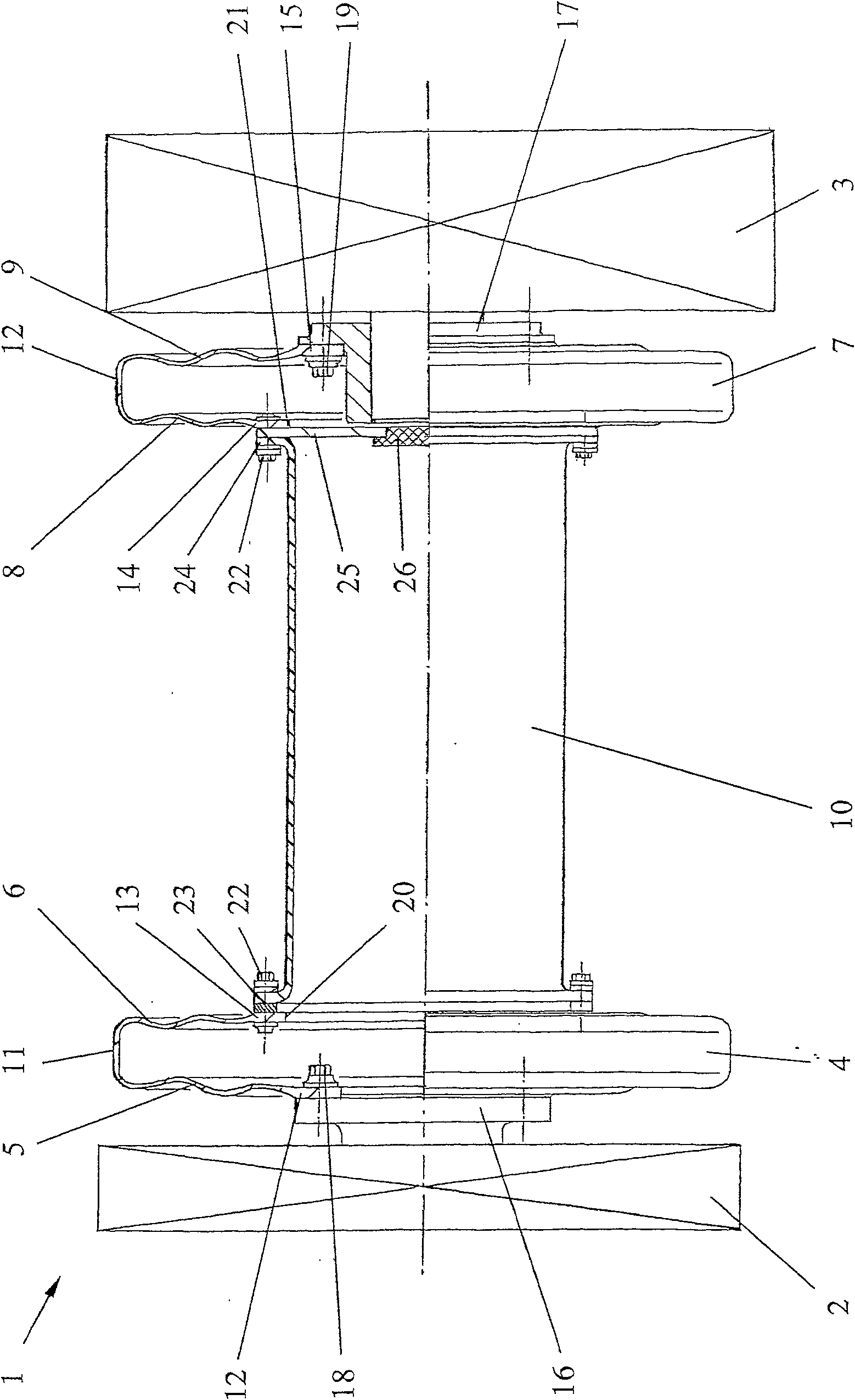
[0030] The first embodiment shows the membrane compensation coupling 1 in the installed state between the elastically fitted motor 2 and the drive unit 3 . The coupling 1 is of block construction and consists of three elements. It comprises a first compensator 4 with two opposing membranes 5 and 6 , a second compensating element 7 with two opposing membranes 8 and 9 , and an intermediate tube 10 embedded between them. The individual elements are manufactured in one piece from fiber composite material. The compensating elements 4 and 7 are always made of resin embedded with glass and / or carbon fibers, depending on the intended use. Although the maximum axial length of the compensating elements 4 and 7 is limited for manufacturing reasons, the intermediate tube 10 can achieve dimensions adapted to the different installation situations.
[0031]The membranes 5 , 6 and 8 , 9 of the compensating elements 4 and 7 are connected to one another at their outer circumferences by substa...
Embodiment 2
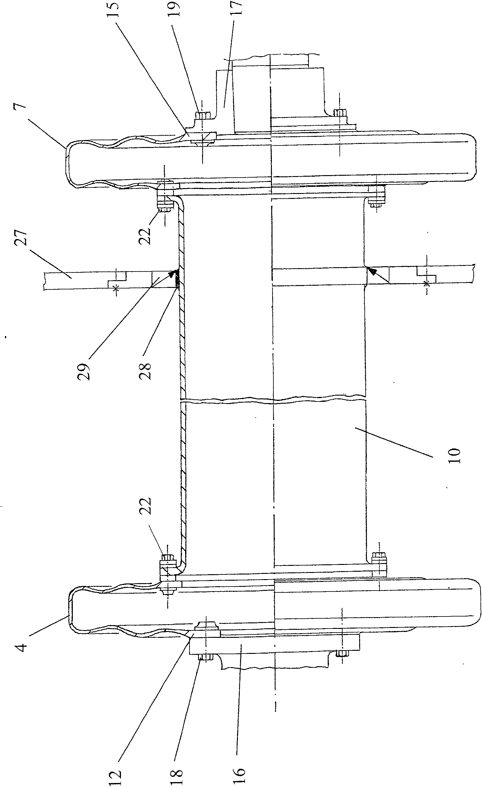
[0037] figure 2 A second embodiment of a membrane compensating coupling is shown in which the compensating elements 4 and 7 are of the same design as the first example. When the distance between the engine and the transmission is long, it is sometimes necessary for the intermediate pipe 10 to pass through the partition wall 27 . In this case, a slightly raised metal or plastic ring 28 is additionally provided on the outer circumference of the intermediate pipe 10 made of fiber composite material, a metal or plastic ring with a radially split sealing ring 29 connected to the partition wall 27 A plastic ring forms a flexible sliding seal.
[0038] During the installation process, the intermediate pipe 10 is now installed first. The compensating elements 4 and 7 are then moved radially into their connected position. Their connection to the intermediate pipe 10 is the same as in the first embodiment. Since the connecting flanges 12 and 15 separated from the intermediate pipe ...
Embodiment 3
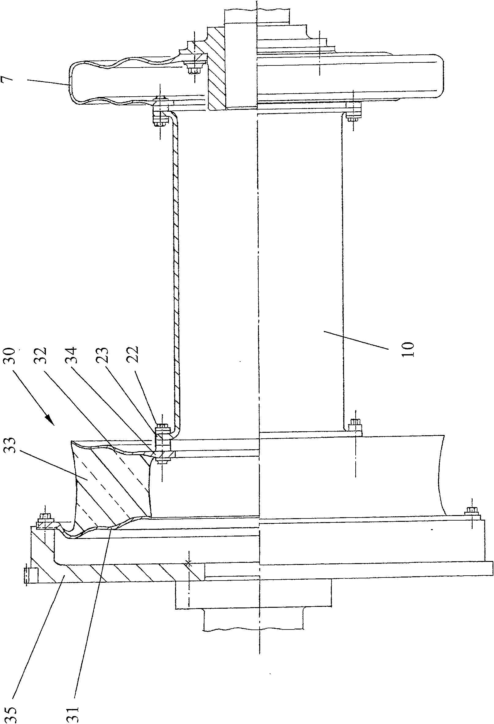
[0040] image 3 A third embodiment is shown in , where a compensating element can be designed as an elastic connecting element 30 . The elastic connection 30 comprises two annular membranes 31 and 32, which are always made of fiber composite material and can be provided with curvature. Elastomer 33 is placed between membranes 31 and 32 and is preferably vulcanized onto the membranes. The membrane 32 facing the central tube 10 has a radially inwardly protruding connecting flange 34 which is of the same design as the connecting flanges 13 and 14 of the two preceding exemplary embodiments. Here too, the connection to the intermediate pipe 10 is via a hole anchor connection 22 . In the embodiment shown, the other membrane 31 is fixed at its outer end to an intermediate flange 35 which may be fixed to the output element of the motor or the input element of the driven unit. However, instead of the intermediate flange 35, it is also possible to connect the membrane 31 to the motor...
PUM
 Abstract
Description
Claims
Application Information
 - R&D
- Intellectual Property
- Life Sciences
- Materials
- Tech Scout
- Unparalleled Data Quality
- Higher Quality Content
- 60% Fewer Hallucinations
Browse by: Latest US Patents, China's latest patents, Technical Efficacy Thesaurus, Application Domain, Technology Topic, Popular Technical Reports.
© 2025 PatSnap. All rights reserved.Legal|Privacy policy|Modern Slavery Act Transparency Statement|Sitemap|About US| Contact US: help@patsnap.com


