
Calibration method for vehicle speed measuring instrument

A technology of speed measurement and calibration method, which is applied in the testing/calibration of speed/acceleration/shock measurement equipment, speed/acceleration/shock measurement, and measurement devices, etc. It can solve the problem of reducing satellite positioning accuracy, satellite inability to locate, gyroscope and The vehicle speed sensor value is not accurate enough to achieve the effect of improving reliability, avoiding calibration operations, and reducing frequent erasing and writing

Inactive Publication Date: 2010-01-06
SHANGHAI ZENITECH ELECTRONICS TECH DEV
View PDF6 Cites 4 Cited by
  • Summary
  • Abstract
  • Description
  • Claims
  • Application Information

AI Technical Summary

Problems solved by technology

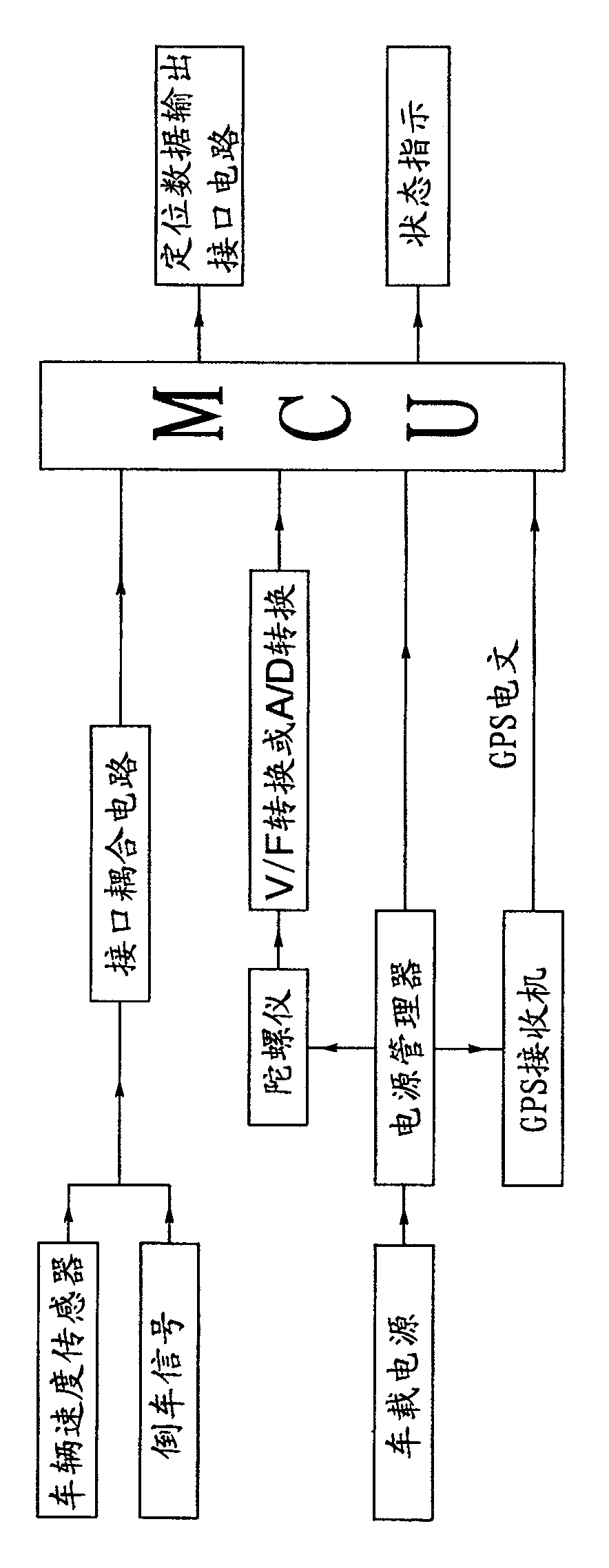
[0002] Due to the increasingly mature satellite positioning technology, more and more satellite positioning and navigation technologies are used by various vehicles. The multi-path effect of radio waves brought by large buildings greatly reduces the positioning accuracy of satellites, and in severe cases, satellites cannot be positioned. The consequence is that continuous and accurate vehicle positioning cannot be provided, which affects the use of satellite navigation systems; in order to solve this problem , in the current vehicle navigation system, the combined positioning technology is widely used, that is, in addition to the use of satellite positioning, the dead reckoning algorithm is also used to measure the heading change of the vehicle according to the angular velocity sensor, the vehicle speed value measured by the speed sensor and GPS or other positioning systems. The reference position provided can be calculated with high accuracy when the satellite positioning is not good, and the continuous positioning signal
[0003] The dead reckoning algorithm can use GPS or other positioning systems to eliminate the cumulative error of dead reckoning, so as to achieve continuous and accurate vehicle positioning and measurement of speed and heading; usually the angular velocity measurement component is a gyroscope, and the vehicle speed measurement component is a vehicle mileage signal , ABS differential signal, engine speed signal and other vehicle speed sensors, due to different circuits, gyro characteristics, vehicle types and vehicle tire wear, in order to meet the accuracy of positioning, it is necessary to carry out the gyroscope and vehicle speed sensor. Calibration; at present, there is no good method to accurately calibrate the errors of the gyroscope and vehicle speed sensor installed on the vehicle site, that is, the values ​​​​obtained by the gyroscope and vehicle speed sensor are not accurate enough

Method used


Image

  • Calibration method for vehicle speed measuring instrument
  • Calibration method for vehicle speed measuring instrument

Examples


Embodiment Construction

[0019] The present invention will be described in detail below with reference to the drawings.

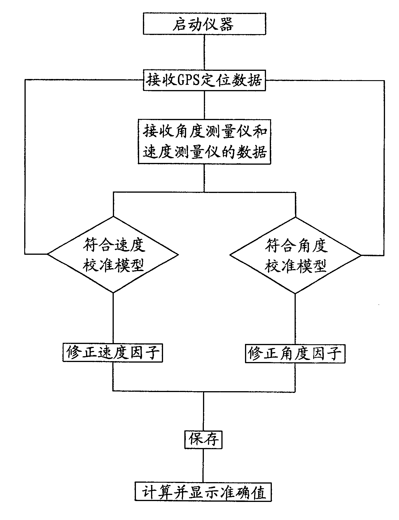
[0020] Such as figure 1 The calibration method of a vehicle-mounted speed measuring instrument shown includes the following steps:

[0021] a. GPS receiver receives GPS positioning data;

[0022] b. The instrument data obtained by the vehicle-mounted speed measuring instrument;

[0023] c. Determine whether the GPS positioning data and meter data meet the conditions of the speed calibration model:

[0024] I. If not, re-receive GPS positioning data and meter data;

[0025] II. If it does, correct the original speed factor of the measuring instrument to obtain a new speed factor and save it; the correction method is: the new angular velocity factor is the product of the ratio of the heading change obtained by the GPS and the measuring instrument and the original angular velocity factor ; The new linear velocity factor is the product of the ratio of the speed obtained by the GPS and the measur...


PUM


Abstract

A method for calibrating vehicle speed measurer includes receiving GPS positioning data by GPS receiver and obtaining instrument data by said speed measurer, judging whether GPS positioning data and instrument data are in accordance to speed calibration model or not, revising speed factor originally set in said speed measurer to obtain new speed factor and storing it then using product of this new speed factor and instrument data as true speed of vehicle if it is or otherwise re-receiving GPS positioning data and instrument data.

Description

Technical field [0001] The invention relates to a method for calibrating a vehicle-mounted speed measuring instrument in dead reckoning for vehicle satellite positioning and navigation. Background technique [0002] Due to the increasing maturity of satellite positioning technology, more and more satellite positioning and navigation technologies are used by various vehicles. However, in practical applications, due to metropolitan viaducts, tunnels, overpasses, etc., satellite signals in many areas are poorly received, and due to urban The multi-channel effect of radio waves brought by large buildings greatly reduces the positioning accuracy of satellites. In severe cases, satellites cannot be positioned. The consequence is that they cannot provide continuous and accurate vehicle positioning, which affects the use of satellite navigation systems; in order to solve this problem In current vehicle navigation systems, combined positioning technology is commonly used, that is, in addi...

Claims


Application Information

Patent Timeline
Patent Type & Authority Patents(China)
IPC IPC(8): G01C25/00G01C21/00G01P21/02G01S1/02G01S5/02G01S19/07
Inventor 何铁夏继江徐亚卿
Owner SHANGHAI ZENITECH ELECTRONICS TECH DEV
Learn More