Liquid control one-way valve for suspension moving top beam hydraulic chock

A technology of hydraulically controlled one-way valve and hydraulic support, which is applied in the direction of mine roof supports, pillars/supports, mining equipment, etc., which can solve the problems of large liquid drainage resistance, poor liquid return, and long time consumption, so as to improve negative pressure resistance Ability, safe and reliable use, and shorten the effect of liquid return time

Inactive Publication Date: 2010-01-20
郑相辅
View PDF5 Cites 0 Cited by
  • Summary
  • Abstract
  • Description
  • Claims
  • Application Information

AI Technical Summary

Problems solved by technology

[0004] The existing hydraulic control check valve has the following problems in actual use: Poor controllability: when the cylinder is lifted, a large amount of pressure fluid stored in the circular cavity of the pillar needs to return from the original path, that is, it must pass through the upper inner cavity 18a, be The sealing surface 15a pushed back by the ejector rod 12a, the middle inner cavity 20a, the supporting liquid injection hole 6a, the control valve and the pipeline can return to the oil tank of the pump station, and the control valve has a very small liquid return channel due to structural reasons, and the liquid discharge resistance is very high Large, so there is the problem of poor liquid return, which leads to slow lifting speed and long time-consuming (I feel that lifting the cylinder is quite difficult on site, it takes about 40-60 seconds to lift the stroke of 800mm, and the annular cavity needs continuous high-pressure liquid supply), and the rack moving efficiency low, which seriously restricts the improvement of the coal mining progress of the coal mining face
In addition, it is easy to drop the cylinder after lifting the cylinder: due to the structure of the valve, the negative pressure resistance of the valve is poor, and the negative pressure generated by the gravity of the support cylinder will make the support refill the cylinder, making the support cylinder drop, making it difficult to move the support. There is a need to re-lift the cylinder
Furthermore, misoperation is easy to occur: when operating other pillars and jacks, the pressure liquid with more than 0.8 MPa in the discharge pipe is easy to enter the pillar of the lifted cylinder through the check valve in the hydraulic control check valve, so that the pillar oil cylinder decline

Method used


Image

  • Liquid control one-way valve for suspension moving top beam hydraulic chock
  • Liquid control one-way valve for suspension moving top beam hydraulic chock

Examples


Embodiment Construction

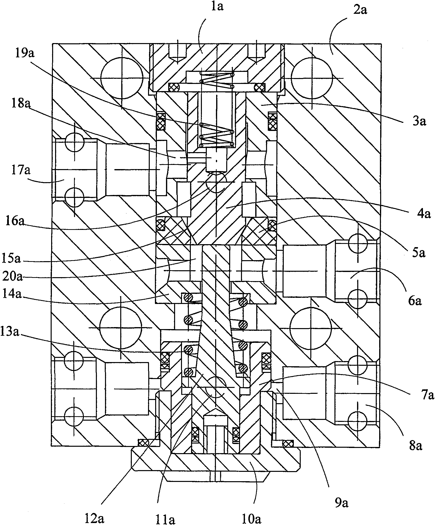
[0014] figure 1 The middle serial numbers represent: upper end cover 1a, valve body 2a, guide sleeve 3a, valve core 4a, valve seat 5a, support liquid injection hole 6a, ejector sleeve 7a, lifting cylinder liquid injection hole 8a, lower inner cavity 9a, lower end cover 10a, annular cavity radial through hole 11a, ejector rod 12a, return spring 13a, bushing 14a, sealing surface 15a, circular cavity radial through hole 16a, pressure gauge hole 17a, upper inner cavity 18a, spring 19a, middle inner The cavity 20a is connected to the screw hole 21a.

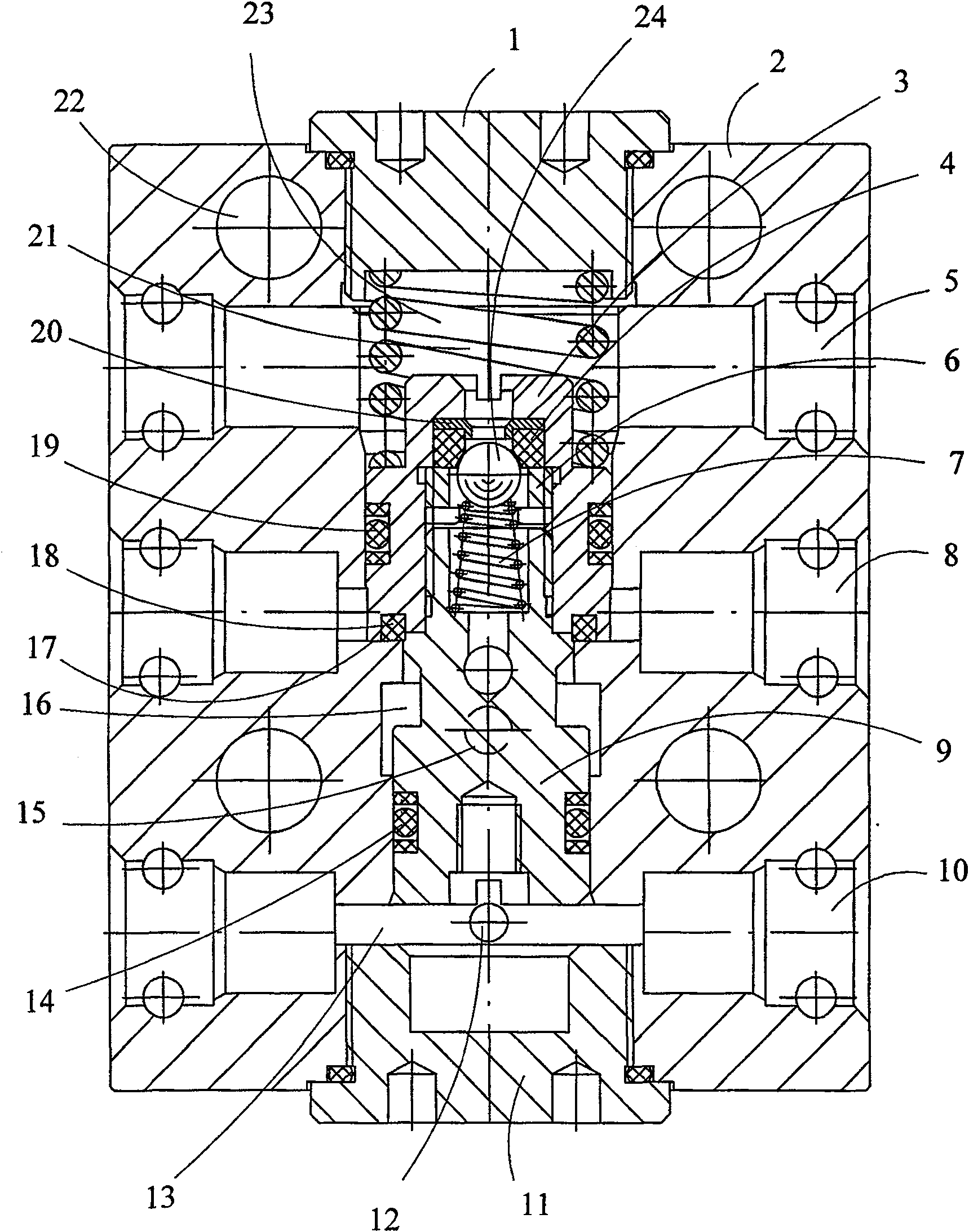
[0015] figure 2 The middle serial numbers represent: upper end cover 1, valve body 2, liquid injection valve body 3, valve seat 4, support liquid injection hole 5, compression screw sleeve 6, conical spring 7, liquid discharge hole 8, valve core 9, lift Cylinder liquid injection hole 10, lower end cover 11, annular cavity radial through hole 12, lower inner cavity 13, sealing assembly 14, circular cavity radial through hole 15, mid...


PUM


Abstract

A pilot-operated one-way valve used in the suspending top beam hydraulic bracket is set with the upper and lower end cover on two ends. The side wall is opened with the supporting filling hole, the outage and lifting jar filling hole. The inner one-way valve is made up of the filling valve body and the steel balls. The valve hollow is divided into the upper, middle and the lower hollows by the inner one-way valve, the plane sealing surface and the sealing module on the valve core. The inner one-way valve is on the channel between the upper hollow and the middle hollow; the plane sealing surface is set on the channel which the supporting circle hollow and the middle hollow to the outage. Because of the dividing design of the supporting filling and the liquid return channel. The pressure liquid can return to the pump oil tank. The lifting jar is quick and the bracket moving efficiency is high. It is especially proper for the bracket with big cylinder diameter and big distance.

Description

technical field [0001] The invention belongs to a valve component for coal mine support equipment, in particular to a hydraulically controlled one-way valve for a hydraulic support of a suspended roof beam. Background technique [0002] The hydraulic control one-way valve (commonly known as the hydraulic control one-way lock) is a kind of assembly on the upper part of the hydraulic support pillar of the suspended roof beam in the coal mine, which is used to control the working fluid entering and leaving the circular cavity and the annular cavity of the pillar, so that the pillar can circulate to complete the support and load. And the unloading lifting cylinder working stage, so as to realize the control parts of the suspension bracket supporting the roof of the coal mining face and advancing forward, and each pillar is equipped with a hydraulic control check valve. The structure of the existing hydraulic control check valve is as follows: figure 1 As shown, it is mainly com...

Claims


Application Information

Patent Timeline
Patent Type & Authority Patents(China)
IPC IPC(8): E21D15/51E21D23/16
Inventor 郑相辅
Owner 郑相辅
Why Eureka
Try Eureka