
Pneumatic control proportioning time-delay change valve

A reversing valve and proportional technology, applied in the field of air-controlled proportional delay reversing devices, can solve the problems of slow action speed, complex structure, low frequency of use, etc., and achieve the effect of continuous adjustment and reduction of overall volume.

Active Publication Date: 2010-01-20
BEIJING AEONMED
View PDF7 Cites 0 Cited by
  • Summary
  • Abstract
  • Description
  • Claims
  • Application Information

AI Technical Summary

Problems solved by technology

At present, the commonly used control methods of delay reversing valves are as follows: electromagnetic control, air pressure control, manual control and mechanical control. There are certain technical problems in these control methods: electromagnetic control delay reversing valves need Provide external power supply; manual control delay reversing valve is too low in automation, it is difficult to accurately control the delay time, and the frequency of use is low, and the action speed is slow; mechanical control delay reversing valve needs the help of cams, bumpers or other The external force provided by the mechanical structure pushes the main spool assembly to move, so as to realize the delayed reversing. The structure required by this control method is too complicated, and the reliability is not high; and the delayed reversing device currently used for air pressure control cannot At the same time, it realizes the continuous adjustment of the reversing frequency and on-off time ratio of the reversing valve. The delay time of the gas output is realized by changing the size of the air chamber and adjusting the intake speed. If the variable volume of the air chamber is too large, then It is bound to increase the overall volume of the reversing valve or make the structure more complicated, and practical applications show that changing the size of the air chamber has little effect on changing the on-off time ratio of the reversing valve

Method used


Image

  • Pneumatic control proportioning time-delay change valve
  • Pneumatic control proportioning time-delay change valve

Examples


Embodiment Construction

[0023] The specific real-time mode of the air-controlled proportional time-delay reversing valve according to the present invention will be described below with reference to the preferred embodiment in the accompanying drawings.

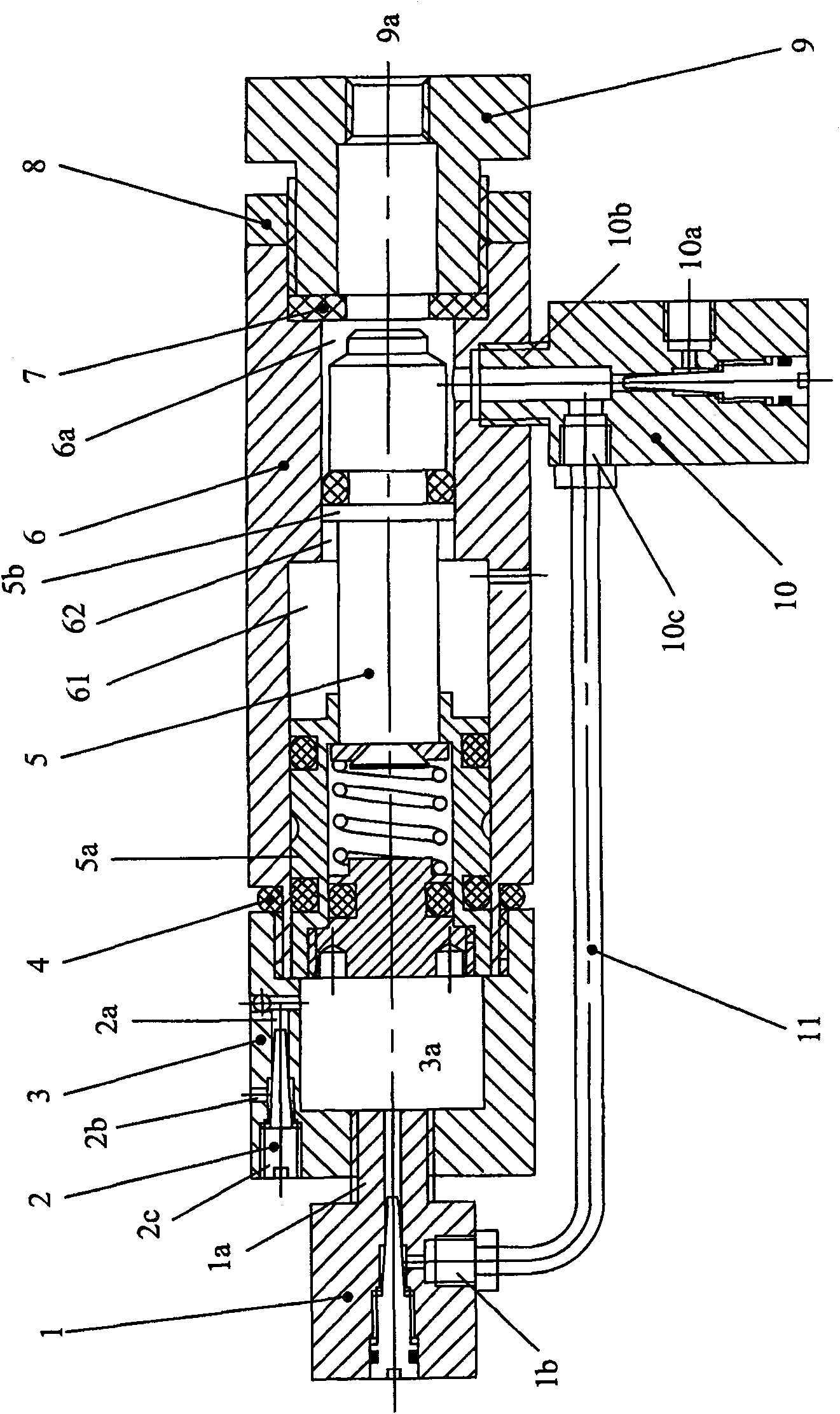
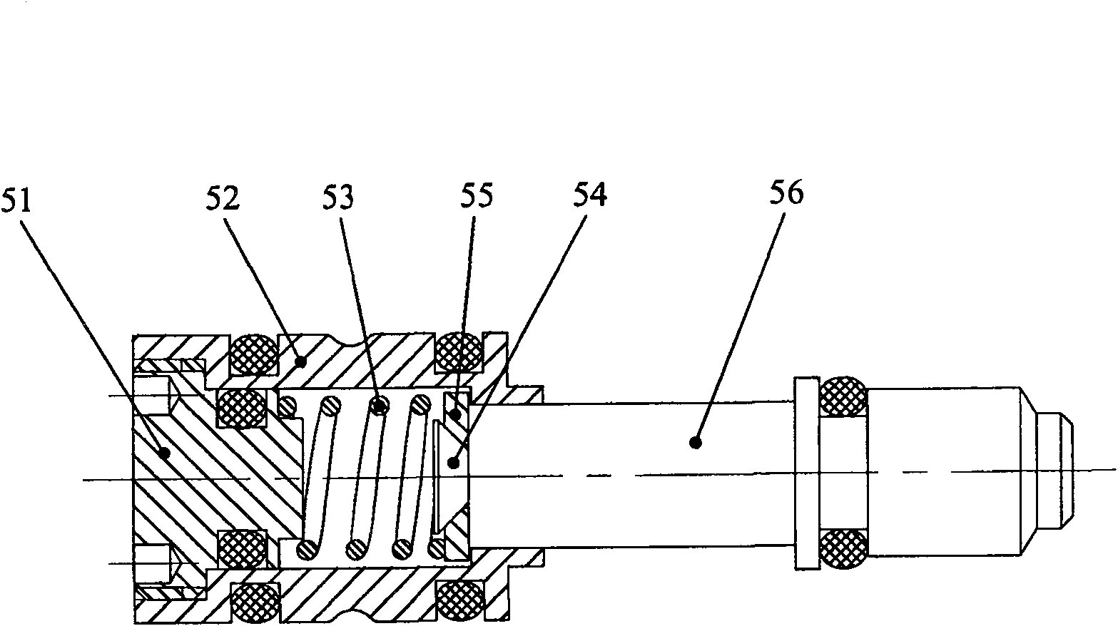
[0024] First refer to figure 1 with figure 2 The specific structure and composition of the air-controlled proportional time-delay reversing valve according to the preferred embodiment of the present invention will be described in detail. figure 1 is a schematic structural diagram of an air-controlled proportional time-delay reversing valve according to a preferred embodiment of the present invention, figure 2 yes figure 1 Schematic diagram of the structure of the main spool assembly of the air-controlled proportional time-delay reversing valve in . Depend on figure 1 As shown, the air-controlled proportional time-delay reversing valve in this preferred embodiment includes: a first throttle valve 1, a second throttle valve 2, a valve cap 3, a ma...


PUM


Abstract

The invention provides a pneumatic control proportion time-delay reversing valve which mainly relates to the field of medical appliance. The pneumatic control reversing valve comprises an inner cavity with a main valve core component (5), a first end with a first air chamber (3a), a second end with a second air chamber (6a), a first throttle valve (1) respectively communicated with the first air chamber (3a) and the second air chamber (6a); a second throttle valve (2) respectively communicated with the first air chamber (3a) and the atmosphere; an air inlet port (9a) which is communicated with the second air chamber (6a) and connected with an external air source as well as an air outlet port (10a) which is communicated with the second air chamber (6a) and the first throttle valve (1). The pneumatic control proportion time-delay reversing valve overcomes the defects of an electric control reversing valve, a manual control reversing valve and a mechanical control reversing valve as well as can continuously adjust the reversing frequency and the on-off time ratio of the pneumatic control proportion time-delay reversing valve in a simple mode.

Description

technical field [0001] The invention relates to an air-controlled proportional time-delay reversing device, in particular to a pneumatic valve which provides signals or pulses with a proportional delay. Background technique [0002] The time-delay reversing valve is mainly used to control the reversing frequency and on-off time ratio of the gas. For example, if it is used in the medical field, when it is equipped on a ventilator, it is mainly used to control the breathing speed of the patient (that is, the gas commutation frequency) and breath time ratio (ie, gas on and off time ratio). At present, the commonly used control methods of delay reversing valves are as follows: electromagnetic control, air pressure control, manual control and mechanical control. There are certain technical problems in these control methods: electromagnetic control delay reversing valves need Provide external power supply; manual control delay reversing valve is too low in automation, it is diffi...

Claims


Application Information

Patent Timeline
Patent Type & Authority Patents(China)
IPC IPC(8): F16K1/00F16K31/12A61M16/20A61M39/22
Inventor 申佑方颜辉
Owner BEIJING AEONMED
Learn More