Imaging method for implementing airborne radar refocusing in system short of high-precision motion compensating system

A motion compensation, airborne radar technology, used in radio wave measurement systems, radio wave reflection/re-radiation, utilization of re-radiation, etc. Improved, good effect, effect of increased azimuth resolution

Inactive Publication Date: 2010-02-10
BEIJING JIAOTONG UNIV
View PDF2 Cites 2 Cited by
  • Summary
  • Abstract
  • Description
  • Claims
  • Application Information

AI Technical Summary

Problems solved by technology

On a high-speed moving platform, it is very difficult to achieve this target
For example, the wavelength used in the L-band is 22-23cm. For an aircraft flying at a speed above 150m / s, it is very difficult to obtain such accurate positioning information.
At present, my country has not established a complete high-precision global positioning and navigation system, and the inertial navigation accuracy inside the airborne platform cannot meet the requirements of radar.
This will inevitably lead to poor control of the phase history parameters of the airborne radar Doppler signal, resulting in unstable radar image quality, blurred defocus and reduced resolution

Method used


Image

  • Imaging method for implementing airborne radar refocusing in system short of high-precision motion compensating system
  • Imaging method for implementing airborne radar refocusing in system short of high-precision motion compensating system
  • Imaging method for implementing airborne radar refocusing in system short of high-precision motion compensating system

Examples


Embodiment Construction

[0023] The present invention will be further described in detail below in conjunction with the accompanying drawings and specific embodiments.

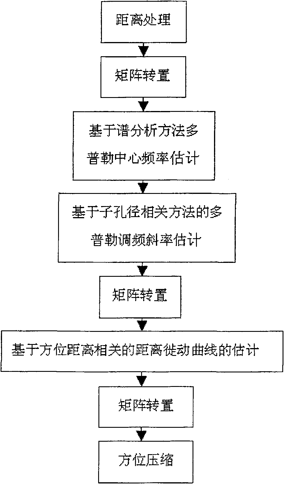
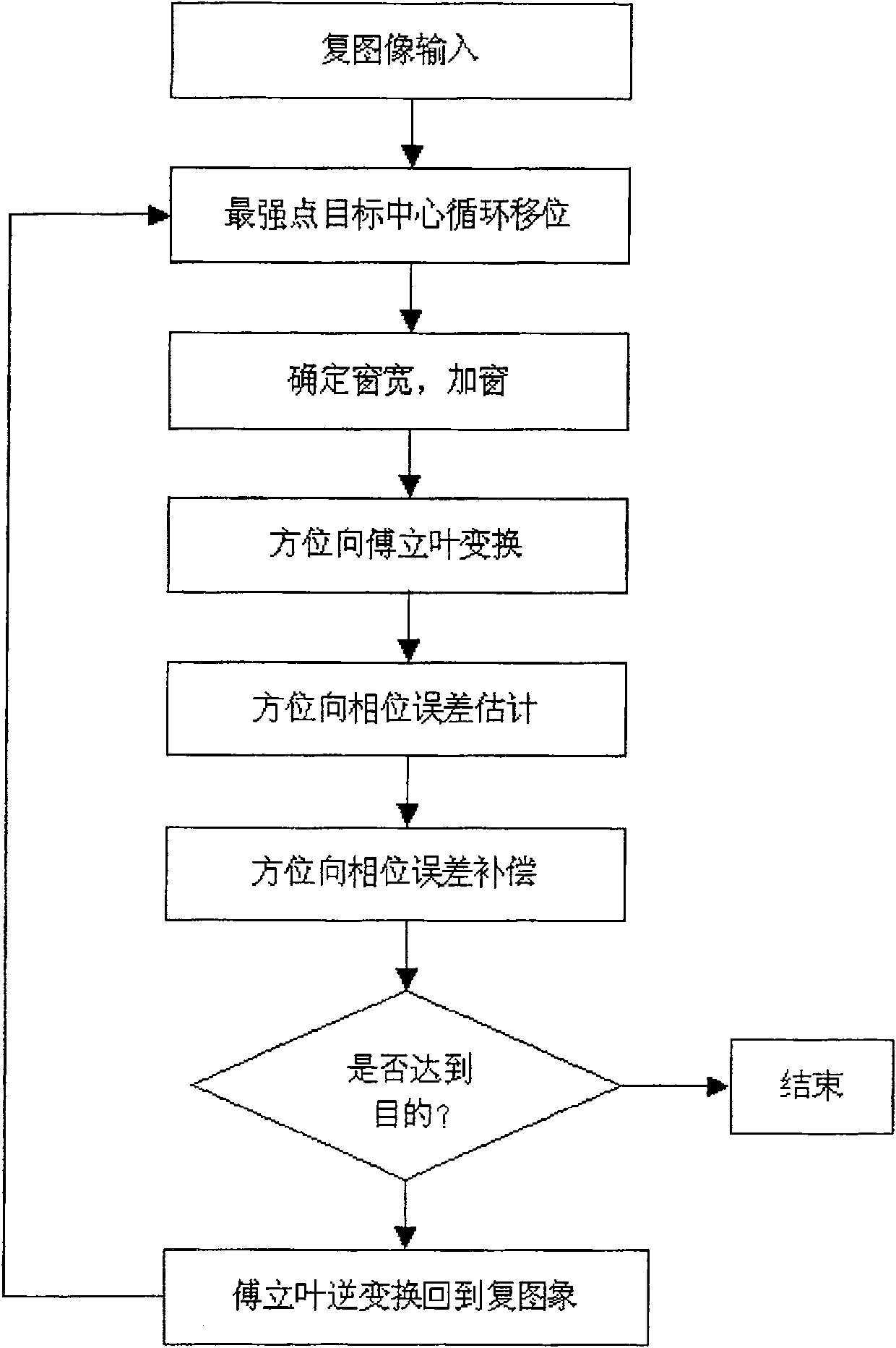
[0024] The raw signal data recorded by the airborne L-SAR raw signal recording system developed by the Institute of Electronics, Chinese Academy of Sciences. The system does not record any aircraft movement information in the signal data because the inertial navigation system is not accurate enough to compensate for motion. Since the entire aperture time of L-SAR is about 20 seconds, it is obviously difficult for the aircraft to fly in a straight line at a constant speed for such a long time. In the absence of a high-precision positioning and navigation system, the control of the signal space sampling time is quite rough, and the Phase stability is difficult to guarantee, seriously affecting the imaging quality. Affected by the random phase error caused by the instability of the aircraft motion, the azimuth resolution of the single-l...


PUM


Abstract

The invention relates to a re-focusing and imaging method for an on-board radar without any hi-precision motion compensation system, which comprises two procedures: (1) SAR initial compound image creation based on de-gradient processing; (2) Doppler signal phase error is measured based on improved PGA arithmetic, and compound image re-focusing for phase compensation is carried out. The second procedure comprises the following steps: the compound images are input; the center of the target with the most intensive point goes through cyclic movement; a window is added; Fourier transformation is done for orientation; estimation is made on the phase error; the phase is corrected; inverse Fourier transformation is done to return the compound image area. The invention allows to get on-board L-SARre-focused images with resolution of orientation obviously improved only by original signal data without any hi-accuracy on-board platform movement compensation system to provide the info on movementstate of an airplane; and the higher the contrast in the images, the better the focusing effect will be. As the SAR wavelength of L wave section is longer and penetrating, the invention can play highrole in military reconnaissance and monitoring any disaster in civil application.

Description

technical field [0001] The invention relates to a method for realizing airborne radar refocusing imaging without a high-precision motion compensation system, and belongs to the technical field of synthetic aperture radar (SAR) signal digital imaging processing. Background technique [0002] Synthetic aperture radar is a type of imaging radar. It is usually installed on moving platforms such as aircraft, spacecraft or satellites, and obtains image information of ground targets by receiving and processing the electromagnetic waves radiated by the radar itself to the ground. As a means of microwave active remote sensing, it has advantages that optical remote sensing methods do not have. First of all, it has all-weather and all-weather working ability so that it is not affected by light and cloud coverage; secondly, due to the coherent characteristics of radar signals, the specially designed synthetic aperture radar can extract the three-dimensional information of the ground, a...

Claims


Application Information

Patent Timeline
Patent Type & Authority Patents(China)
IPC IPC(8): G01S13/90G01S7/02
Inventor 谭衢霖胡吉平
Owner BEIJING JIAOTONG UNIV
Why Eureka
Try Eureka