Eureka AIR delivers breakthrough ideas for toughest innovation challenges, trusted by R&D personnel around the world.

Oil gas separator

A technology of oil mist separation and oil outlet, which is applied in the direction of engine lubrication, metal rolling, mechanical equipment, etc., can solve the problems of poor lubrication effect and large bubble content, and achieve cost saving, consumption saving and good lubrication effect. Effect

Inactive Publication Date: 2007-07-18
郑星昱
View PDF0 Cites 0 Cited by
  • Summary
  • Abstract
  • Description
  • Claims
  • Application Information

AI Technical Summary

Problems solved by technology

[0004] The object of the present invention is to provide an oil mist separation device for the above-mentioned existing backing bearing roller lubricating oil mist sprayed directly from the oil outlet hole, large bubble content and poor lubricating effect, which can separate the lubricating oil The oil and steam in the mist are separated to improve the lubrication effect

Method used


Image

  • Oil gas separator
  • Oil gas separator

Examples


Embodiment Construction

[0020] The technical solutions of the present invention will be described in further detail below with reference to the accompanying drawings and embodiments.

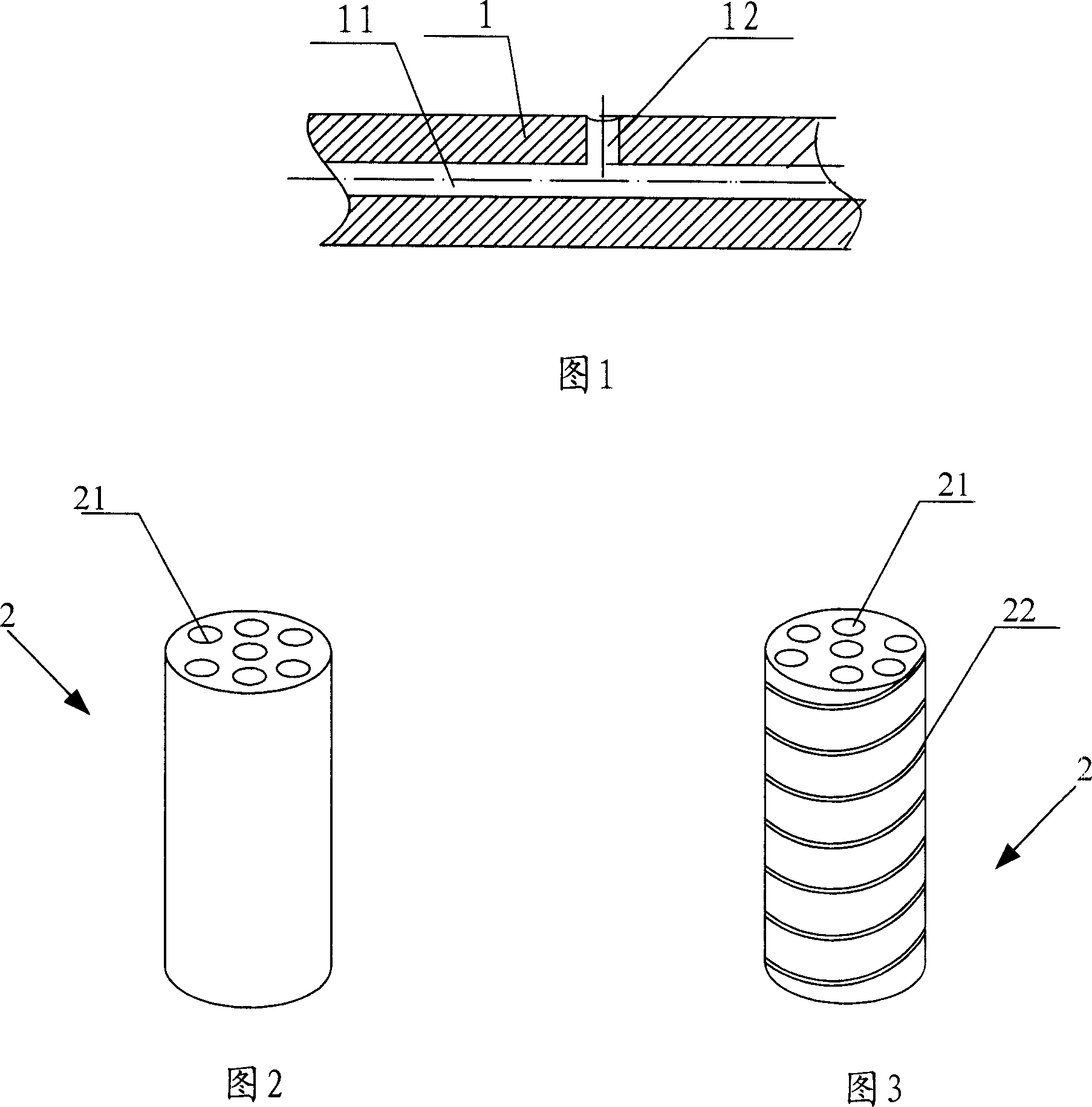
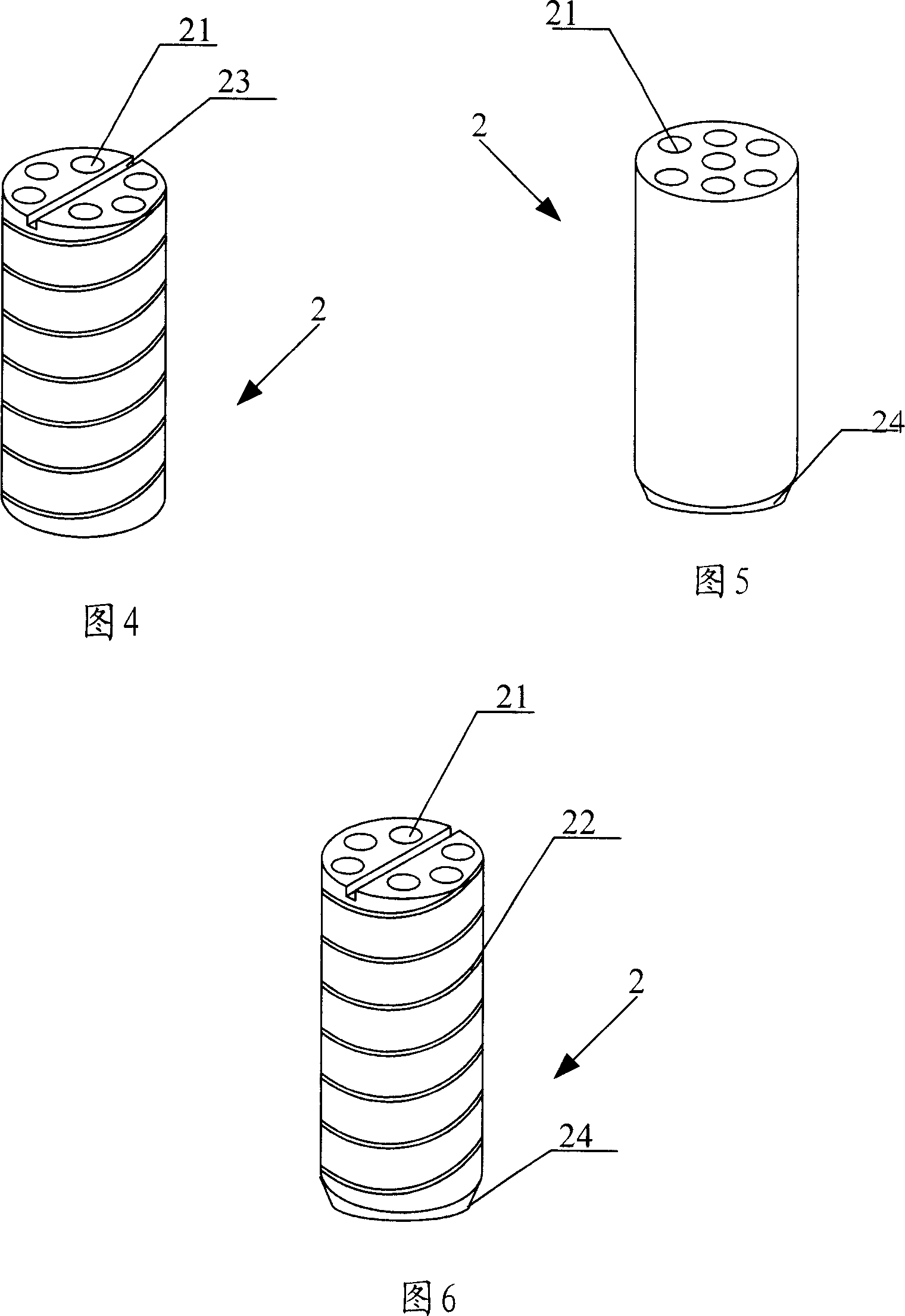
[0021] Fig. 2 is a schematic structural view of the first embodiment of the oil mist separation device of the present invention. The oil mist separation device 2 is arranged in the oil outlet hole 12 in Fig. 1, the shape of the oil outlet hole 12 is a cylinder, and the oil mist separation device 2 is a cylinder matching the shape of the oil outlet hole 12, and its upper and lower bottom surfaces Between them, one or more oil mist separation holes 21 are axially penetrated inside the cylinder, and the oil mist separation device 2 can be firmly installed in the oil outlet hole 12 through interference fit.

[0022] Fig. 3 is a schematic structural view of the second embodiment of the oil mist separation device of the present invention. The oil mist separation device 2 is a cylinder with one or more oil mist separation ho...


PUM


Abstract

The invention relates to an oil gas separator, and it is a column matching with oil outlet shape and having one or multiple axial through micropores. And it can separate oil and vapor in the lubricating oil gas and improve lubricating effect.

Description

technical field [0001] The invention relates to an oil mist separation device, in particular to an oil mist separation device which can improve the lubricating effect and is used in the backing bearing roll of a plate and strip mill. Background technique [0002] In the manufacture and use of plate and strip mills, backing bearing rolls are usually used to support the intermediate support rolls. Some of the existing backing bearing roll cores use a through shaft, and bearings are fixed in sections on it. Some divide the original through shaft into multiple sections, and install a bearing on each section of the shaft. However, no matter whether the integral shaft or the segmented shaft is used, due to the friction on the surface during the mutual rotation of the roller core and the bearing, the working efficiency of the roller system of the rolling mill is reduced and the service life of the backing bearing roller is reduced. Therefore, as shown in Figure 1, usually a lubric...

Claims


Application Information

Patent Timeline
IPC IPC(8): F16N7/32F16N39/00B21B27/06
Inventor 郑红专赵林珍
Owner 郑星昱
Why Eureka
Eureka Blog
Learn More