Walking beam changing method of step-by-steep heating furnace

A technology of walking heating furnace and replacement method, applied in lighting and heating equipment, furnace, furnace components and other directions, can solve the problems of affecting production capacity ratio, high replacement cost, bending deformation of column, etc., to increase product efficiency and reduce Maintenance costs, the effect of improving the production capacity ratio

Inactive Publication Date: 2007-07-18
SHANXI TAIGANG STAINLESS STEEL CO LTD
View PDF0 Cites 4 Cited by
  • Summary
  • Abstract
  • Description
  • Claims
  • Application Information

AI Technical Summary

Problems solved by technology

[0002] The walking heating furnace is an essential and important equipment for hot continuous rolling in iron and steel enterprises. The walking heating furnace has been put into operation for four years, and the wall thickness of the horizontal beam water pipe in the flame section has been seriously reduced. The thinnest point is 6-7mm. Severe water leakage occurred, resulting in the forced shutdown of the furnace for emergency repairs
Due to the internal stress of the column due to long-term high temperature, after the horizontal beam is cut and removed, the column will be severely bent and deformed immediately, resulting in the inability to connect the horizontal beam to the column, and the horizontal beam to the horizontal beam. The installation technical requirements cannot be guaranteed. The flame section of the horizontal beam, but the existing walking beam replacement method of the walking heating furnace adopts the method of replacing the horizontal beam and the column as a whole, and it is carried out simultaneously with the overhaul of the furnace body
Every single furnace needs to be shut down for about 72 hours for emergency repairs, and the loss of production capacity and benefits is about 5.76 million yuan per year. The replacement cost is high, which seriously affects the safe operation of production
It takes 104 days to replace all the refractory materials of the furnace body and all the horizontal beams in the flame section of the 35-meter-long and 9.4-meter-wide flame section, which seriously affects the production capacity ratio.

Method used


Image

  • Walking beam changing method of step-by-steep heating furnace
  • Walking beam changing method of step-by-steep heating furnace
  • Walking beam changing method of step-by-steep heating furnace

Examples


Embodiment Construction

[0061] The specific implementation of the method for replacing the walking beam of the walking heating furnace will be described in detail below in conjunction with the embodiments and accompanying drawings, but the method for replacing the walking beam of the walking heating furnace is not limited to the following embodiments.

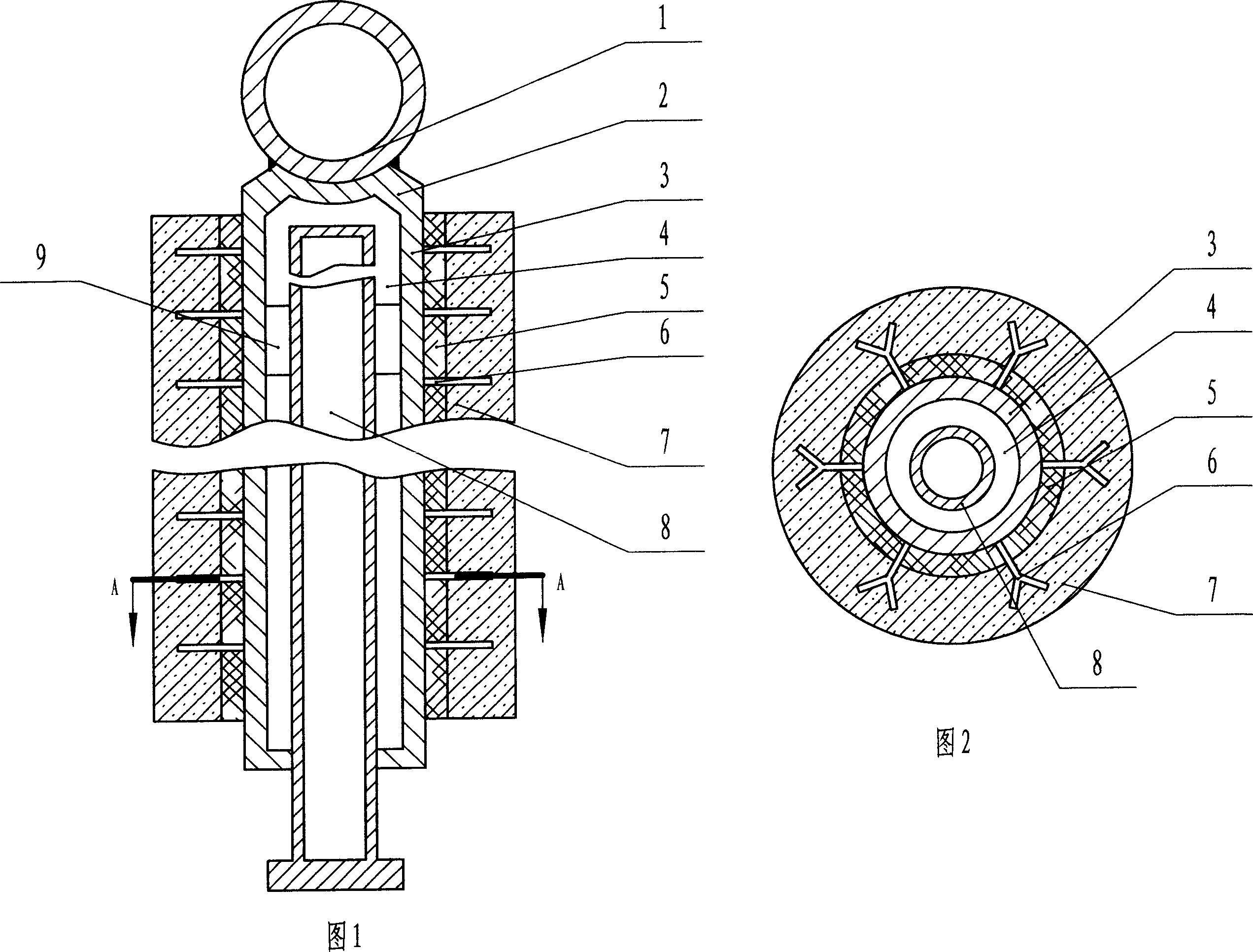
[0062] In this embodiment, a walk-in heating furnace with a length of 35m and a width of 9.4m is replaced. The length of the flame section is 23m, the length of the movable horizontal beam is 35m, the length of the movable horizontal beam of the flame section is 23m, the length of the fixed horizontal beam of the flame section is 23m, and the height of the column of the fixed beam 2.2m, the horizontal beam water pipe is 15000 mm long, the outer diameter is Φ163 mm, and the thickness is 20 mm. The movable beam column water pipe is 4389 mm long, the outer diameter is Φ163 mm, and the thickness is 20 mm.

[0063] The walking heating furnace column describ...


PUM


Abstract

The invention relaters to walking beam exchanging method for the walking beam reheating furnace. It includes the following steps: removing the refractory materials covered on the level beam flame section; removing the fireclay insulating refractory covered on its stand column; fixing walking beam frame to make the error be not more than +/-2mm for all slides along the elevation direction; fixing the stand column each of which upper end is welded strip steel; removing the flame section level beam; cutting flame section saddle shape bracket; welding the bracket of which upper arc surface bottom error is +/-1mm; setting welded level beam tube of which heat resisting cushion block scale height error is not more than +/-2mm; checking the welding port; welding the heat resisting cushion; welding the anchor fixing hook; binding up fiber blanket; pouring; and drying oven. The invention has the advantages of short exchanging construction period, and low cost.

Description

technical field [0001] The invention relates to a method for replacing a walking beam of a walking heating furnace. Background technique [0002] The walking heating furnace is an essential and important equipment for hot continuous rolling in iron and steel enterprises. The walking heating furnace has been put into operation for four years, and the wall thickness of the horizontal beam water pipe in the flame section has been seriously reduced. The thinnest point is 6-7mm. Severe water leakage occurred, resulting in the forced shutdown of the furnace for emergency repairs. Due to the internal stress of the column due to long-term high temperature, after the horizontal beam is cut and removed, the column will be severely bent and deformed immediately, resulting in the inability to connect the horizontal beam to the column, and the horizontal beam to the horizontal beam. The installation technical requirements cannot be guaranteed. The flame section of the horizontal beam, b...

Claims


Application Information

Patent Timeline
Patent Type & Authority Applications(China)
IPC IPC(8): F27D3/12
Inventor 杨福瑞
Owner SHANXI TAIGANG STAINLESS STEEL CO LTD
Why Eureka
Try Eureka