Vacuum load switch and combined electrical equipment

A technology for combining electrical appliances and vacuum loads, which is applied in the direction of electric switches, high-voltage air circuit breakers, high-voltage/high-current switches, etc., and can solve problems such as difficult assembly, inconvenient use, and small installation space for poles

Active Publication Date: 2007-07-18
江苏德春电力科技股份有限公司
View PDF0 Cites 12 Cited by
  • Summary
  • Abstract
  • Description
  • Claims
  • Application Information

AI Technical Summary

Problems solved by technology

[0002] The existing vacuum load switch and fuse are separated, and the user can only connect it on the switch cabinet, which brings inconvenience to the user; the operating mechanism, isolation knife switch and vacuum interrupter in some vacuum load switches are fixed inside the In the sealed box of zero gauge pressure SF6 gas to prevent moisture intrusion and improve reliability, but SF6 gas is a greenhouse gas, and its greenhouse effect is 2500 times that of carbon dioxide, which has a greater impact on the environment and does not meet environmental protection requirements; in addition, the current Some vacuum load switches use soft connections at the moving end of the vacuum interrupter and the connection end of the isolation knife switch. Since the soft connection is electrified, the user can only add an insulating partition to separate the busbar room from the cable room, reducing the load on the switch. The protection level of the cabinet brings inconvenience to the user; at the same time, due to the small installation space of the pole of the load switch, the guide gap of the moving end of the vacuum interrupter is also small, and the bellows of the vacuum interrupter are also very small when the soft connection is fastened. Cannot bear force, so it is difficult to assemble

Method used


Image

  • Vacuum load switch and combined electrical equipment
  • Vacuum load switch and combined electrical equipment
  • Vacuum load switch and combined electrical equipment

Examples


Embodiment Construction

[0016] The present invention is described in further detail below in conjunction with the embodiment that accompanying drawing provides.

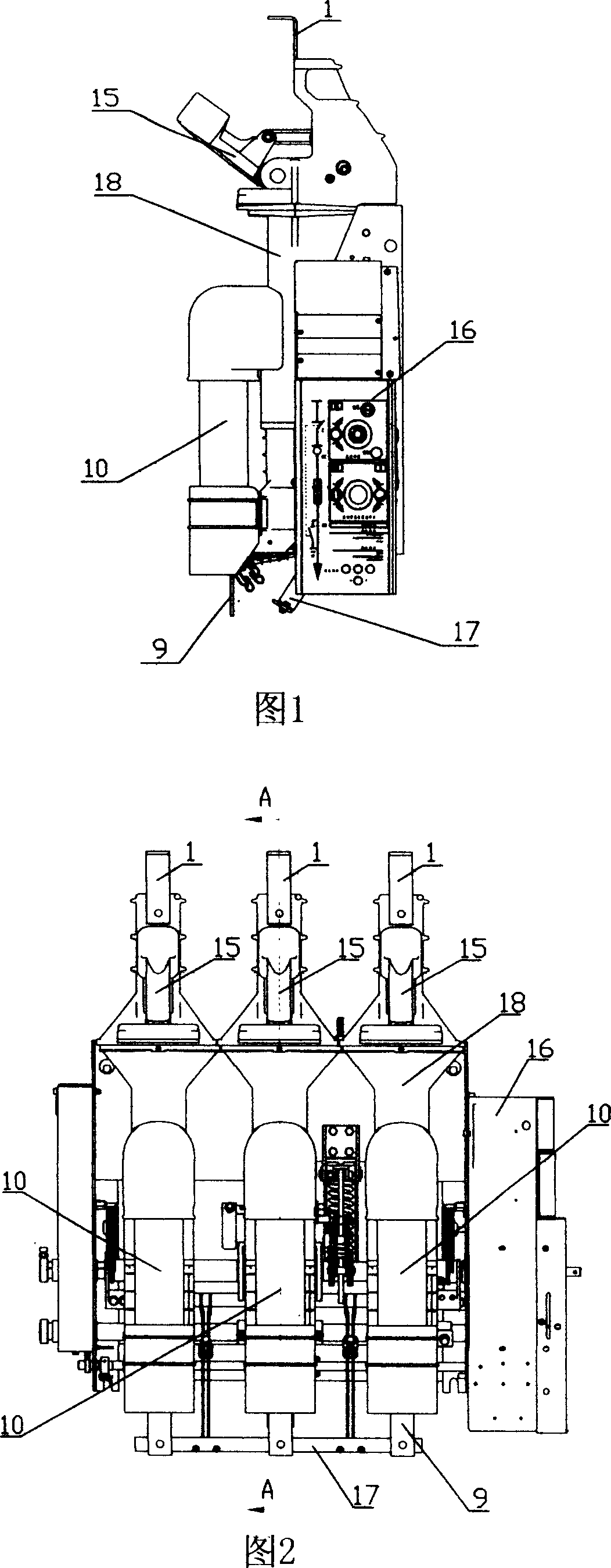
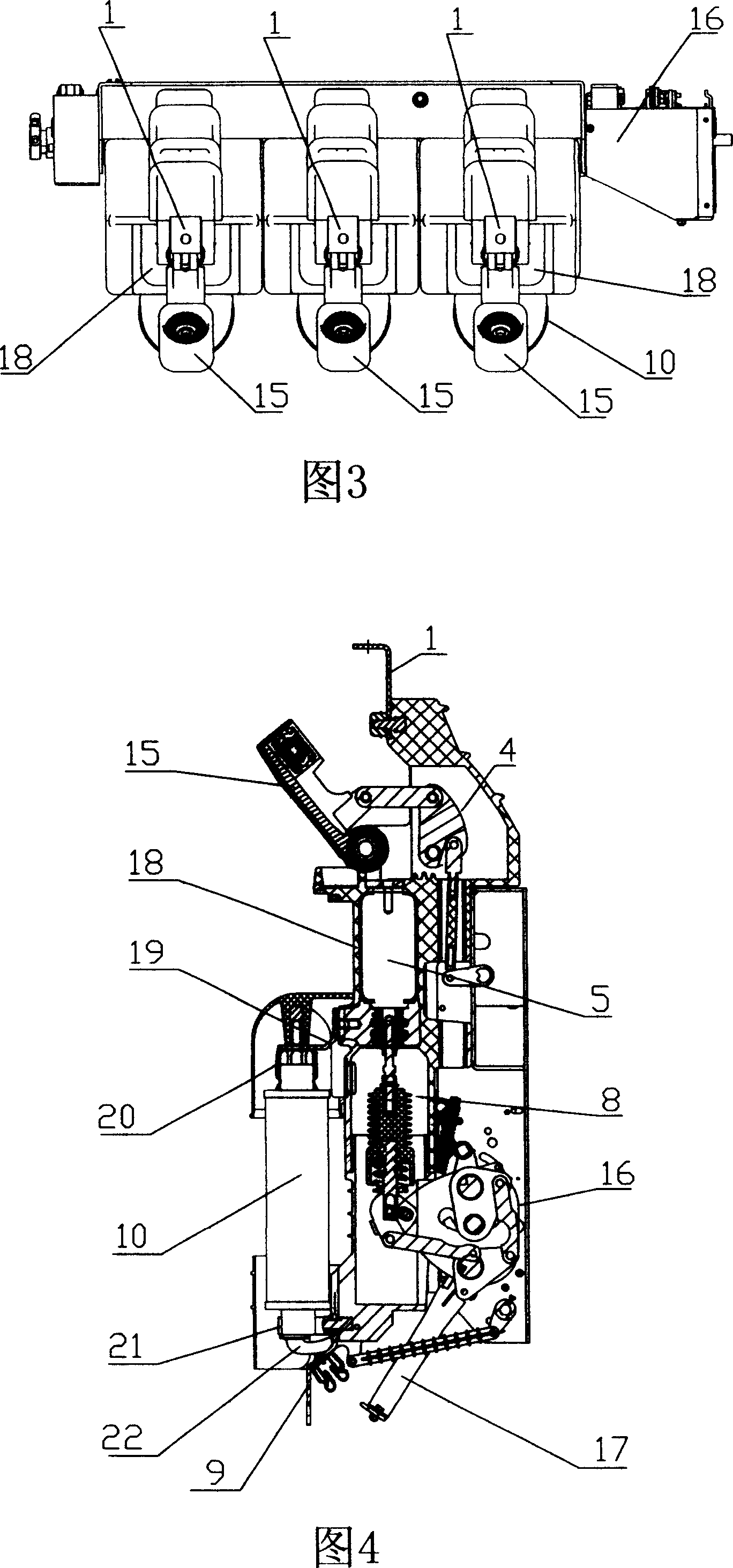
[0017] As shown in Figures 1, 2, 3, 4, and 5, a vacuum load switch and a combined electrical appliance of the present invention include an upper outlet line 1 of a knife switch, an isolation knife switch 15, an isolation knife seat 13, a vacuum interrupter 5, a lower The moving contact 11, the lower outlet seat 12, the cable outlet plate 9, the isolation knife insulation pull rod assembly 4, the arc extinguishing chamber insulation pull rod assembly 8, the operating mechanism 16 and the grounding device 17, the isolation knife switch 15 is connected in series with the vacuum interrupter 5, The isolation knife insulation pull rod assembly 4 and the arc extinguishing chamber insulation pull rod assembly 8 are both in transmission connection with the operating mechanism 16, the isolation knife seat 13, the vacuum interrupter 5 and the lower out...


PUM


Abstract

A vacuum load switch is prepared as series-connecting isolation blade switch to vacuum arc distinguishing chamber, drive-connecting insulation drawing rod of isolation blade switch and insulation drawing rod of arc distinguishing chamber to operation mechanism, firm-sealing isolation blade seat and vacuum arc distinguishing chamber as well as bottom wire outgoing seat together, series-connecting fuse between bottom wire outgoing seat and cable outgoing plate.

Description

technical field [0001] The invention relates to a high-voltage fixed switch cabinet, in particular to a vacuum load switch. Background technique [0002] The existing vacuum load switch and fuse are separated, and the user can only connect it on the switch cabinet, which brings inconvenience to the user; the operating mechanism, isolation knife switch and vacuum interrupter in some vacuum load switches are fixed inside the In the sealed box of zero gauge pressure SF6 gas to prevent moisture intrusion and improve reliability, but SF6 gas is a greenhouse gas, and its greenhouse effect is 2500 times that of carbon dioxide, which has a greater impact on the environment and does not meet environmental protection requirements; in addition, the current Some vacuum load switches use soft connections at the moving end of the vacuum interrupter and the connection end of the isolation knife switch. Since the soft connection is electrified, the user can only add an insulating partition ...

Claims


Application Information

Patent Timeline
Patent Type & Authority Applications(China)
IPC IPC(8): H01H33/66H01H33/664H01H33/666
Inventor 范雄
Owner 江苏德春电力科技股份有限公司
Why Eureka
Try Eureka