System and method for lowering load of enterprise service bus

An enterprise service bus and business system technology, applied in the field of systems that reduce the load of the enterprise service bus, can solve problems such as overloading the bus, and achieve the effect of reducing the load and operating efficiently

Inactive Publication Date: 2007-07-18
HUAWEI TECH CO LTD
View PDF0 Cites 9 Cited by
  • Summary
  • Abstract
  • Description
  • Claims
  • Application Information

AI Technical Summary

Problems solved by technology

In this way, it can be said that the combination of point-to-point connection and bus control is used to solve the problem of overloading the bus and becoming a bottleneck.

Method used


Image

  • System and method for lowering load of enterprise service bus
  • System and method for lowering load of enterprise service bus
  • System and method for lowering load of enterprise service bus

Examples


no. 1 approach

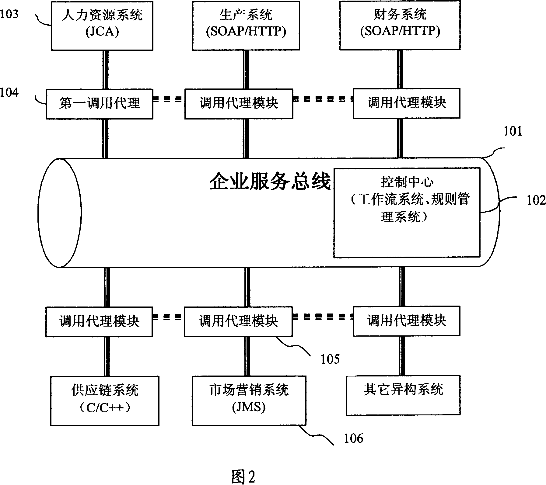
[0034] Fig. 2 is a schematic diagram of the system structure of the first embodiment of the system of the present invention. As shown in Fig. 2, a certain enterprise has a plurality of heterogeneous information management systems, wherein the human resources system 103 is connected based on Java2 Enterprise Edition (J2EE) The production system is realized based on SOAP / HTTP; the financial system is realized based on SOAP / HTTP; the supply chain system is realized based on C / C++; the marketing system 106 is based on Java message middleware JMS Achieved. The present invention adds invoking proxy modules 104, 105 between each information management system and the enterprise service bus 101, and utilizes the original network to interconnect each invoking proxy module. To realize the sequence diagram, the human resource system 103 needs the assessment data of the marketing personnel in the marketing system 106, and the human resource system 103 sends a data call request to the marke...

no. 2 approach

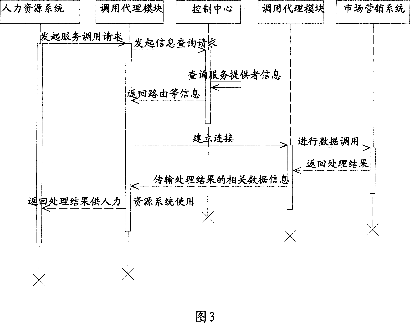
[0036] Fig. 4 is a flow chart of the specific implementation of the second embodiment of the method of the present invention. Specific steps are as follows:

[0037] S201: The human resource system sends a service call request to the marketing system via the first call agent module;

[0038] S202: After receiving the service call request, the first calling agent module sends a marketing system information query request to the control center located on the enterprise service bus; similarly, the control center can also be independent of the enterprise service bus;

[0039] S203: The control center searches for the control information of the marketing system through the workflow management system or the rule management system;

[0040]S204: The control center reads the registration information of the workflow management system or the rule management system, or directly reads the configuration file, and sends the IP address of the marketing system, routing information, and busine...


PUM


Abstract

This invention discloses a service call system based on enterprise service bus including the following modules: a control module, a first call proxy module, a second call proxy module and a service process module, in which, the first one is used in receiving a service call request sent to a second service process module from a first service process module connected with it and asks for the control information of the second service process module to the control module via an enterprise service bus and sends the call request to the second module based on said control information to return the call result to the first module, the second call proxy module is used in receiving the service call request sent to the second service process module by the first proxy module and transfers said request to second process module to transmit the result from the second process module to the first proxy module, the control module is used in returning the control information of the second service process module to the first proxy module via the service bus.

Description

technical field [0001] The invention belongs to the technical field of service-oriented architecture (SOA), and specifically relates to a system and method for reducing the load of an enterprise service bus (Enterprise ServiceBus, ESB). Background technique [0002] With the advancement of technology and the development of society, competitive pressure and ever-changing technology have fundamentally changed the operating rhythm of enterprises. To provide the flexibility that today's real-time enterprises so desperately need, we need a hybrid messaging model that combines the benefits of Web services with traditional asynchronous messaging. The concept of enterprise service bus emerges as the times require, and its system structure is shown in Figure 1. Multiple heterogeneous information management systems, such as human resource systems, production systems, and financial systems, are all connected to the enterprise service bus, and the enterprise service bus completes async...

Claims


Application Information

Patent Timeline
IPC IPC(8): H04L12/40
Inventor 陈琛王京东许波侯伟奕
Owner HUAWEI TECH CO LTD
Why Eureka
Try Eureka