
Switching method and system

A technology for terminal handover and handover confirmation, applied in the field of communication, can solve problems such as large delay, and achieve the effect of reducing interruption delay

Inactive Publication Date: 2007-07-18
HUAWEI TECH CO LTD
View PDF0 Cites 13 Cited by
  • Summary
  • Abstract
  • Description
  • Claims
  • Application Information

AI Technical Summary

Problems solved by technology

[0044] The present invention provides a handover method and system to solve the problem of excessive time delay in the handover process existing in the prior art

Method used


Image

  • Switching method and system
  • Switching method and system
  • Switching method and system

Examples


Embodiment 1

[0143] As shown in Figure 7, it is a schematic diagram of the handover process of Embodiment 1 of the present invention. In Embodiment 1, there is no interface between the SNB and the TNB, and the data needs to be forwarded by the GW. As can be seen from the figure, it mainly includes the following steps:

[0144] S11. The terminal sends a measurement report to the SNB, triggering a terminal handover procedure.

[0145] When the terminal is about to perform handover, it sends a measurement report to the SNB, and sends relevant information of the terminal to the SNB through the measurement report, so as to trigger a terminal handover process.

[0146] S12. The SNB makes a handover decision (HO decision).

[0147] The SNB makes a HO decision according to the measurement report, and decides whether to perform handover according to the relevant data information given in the measurement report.

[0148] S13. The SNB sends a Handover Preparation Request to the TNB.

[0149] The SN...

Embodiment 2

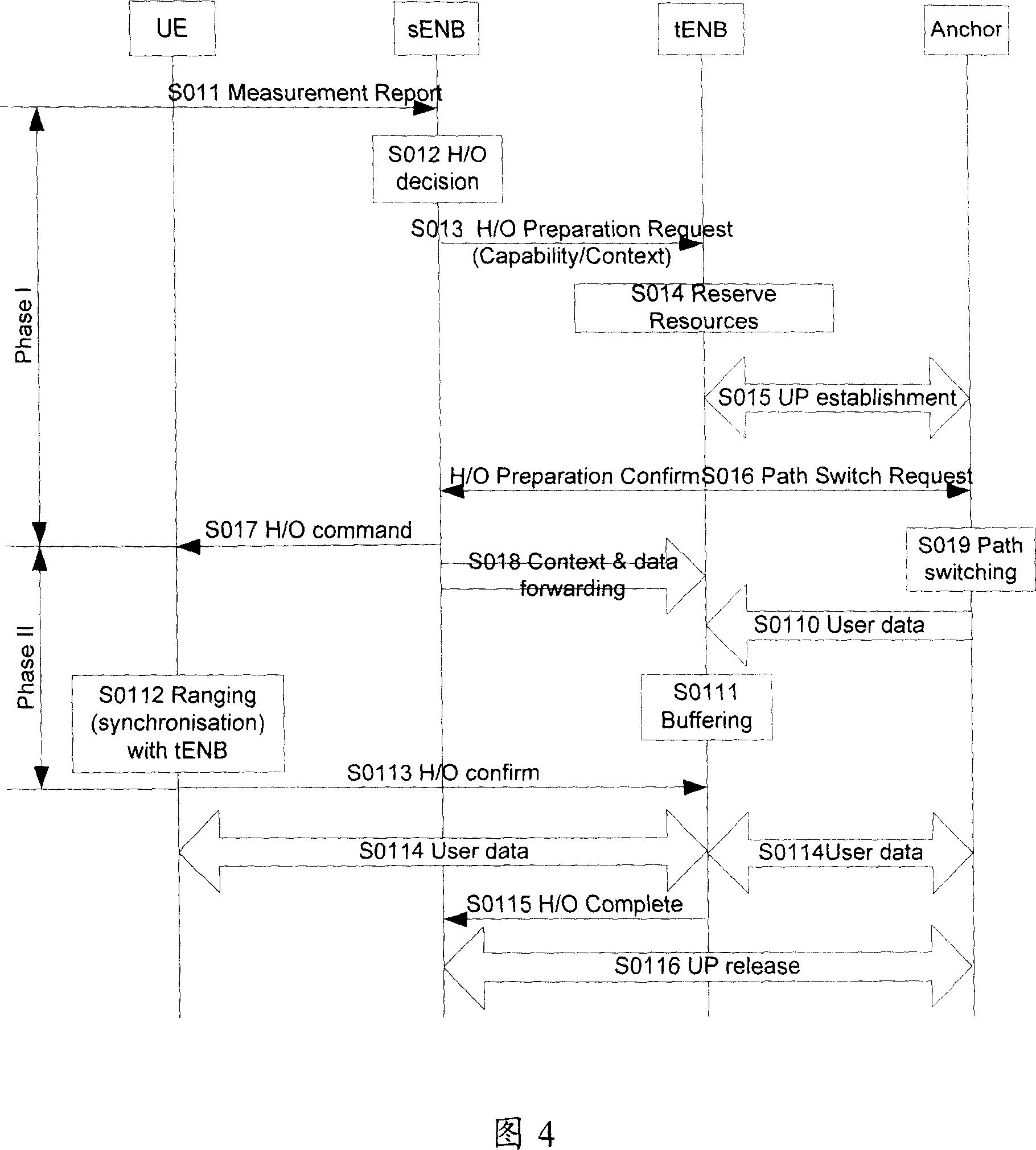
[0179] As shown in Figure 8, it is a schematic flow chart of Embodiment 2 of the present invention. As can be seen from the figure, Embodiment 2 includes the following steps:

[0180] S21. The terminal sends a measurement report to the SNB, triggering a terminal handover process.

[0181] S22. The SNB makes a handover decision.

[0182] S23. The SNB sends a Handover Preparation Request to the TNB.

[0183] S24. The TNB sends path switch requests to the GW.

[0184] S25. The GW sends the Path switch indication to the SNB.

[0185] S26. The SNB activates the numbering function.

[0186] S27. The SNB sends the transmitted context information to the TNB.

[0187] S28. The SNB sends a HO command to the UE, and the UE starts an L1 synchronization process, preparing to establish a wireless connection with the TNB.

[0188] S29. The SNB transmits the terminal context data to the TNB and the terminal.

[0189] S210, UE sends HO confirm to TNB.

[0190] After receiving the handover...


PUM


Abstract

This invention discloses a switch method including: A, a terminal sends a measurement report to a source play node, which exchanges information with a target play node for preparing terminal switch, B, the source node transmits context data to the target node and stores them, C, the target node carries out the switch operation, D, the terminal judges if the switch is succeeded, if so, the terminal sends the confirmation message to the target node, otherwise enters into step E, E, the terminal sends a fault message to the source node. This invention also discloses a switch system.

Description

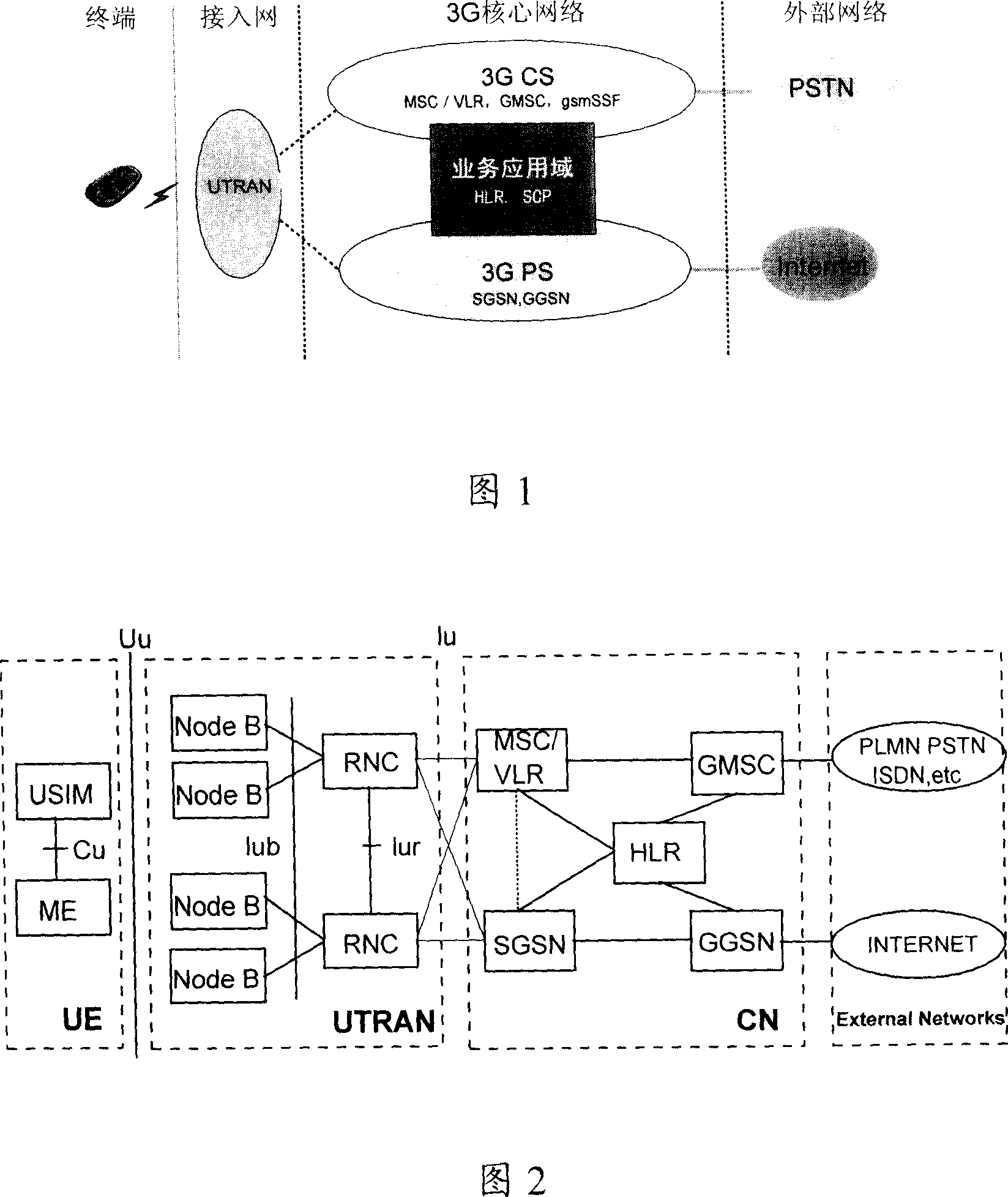
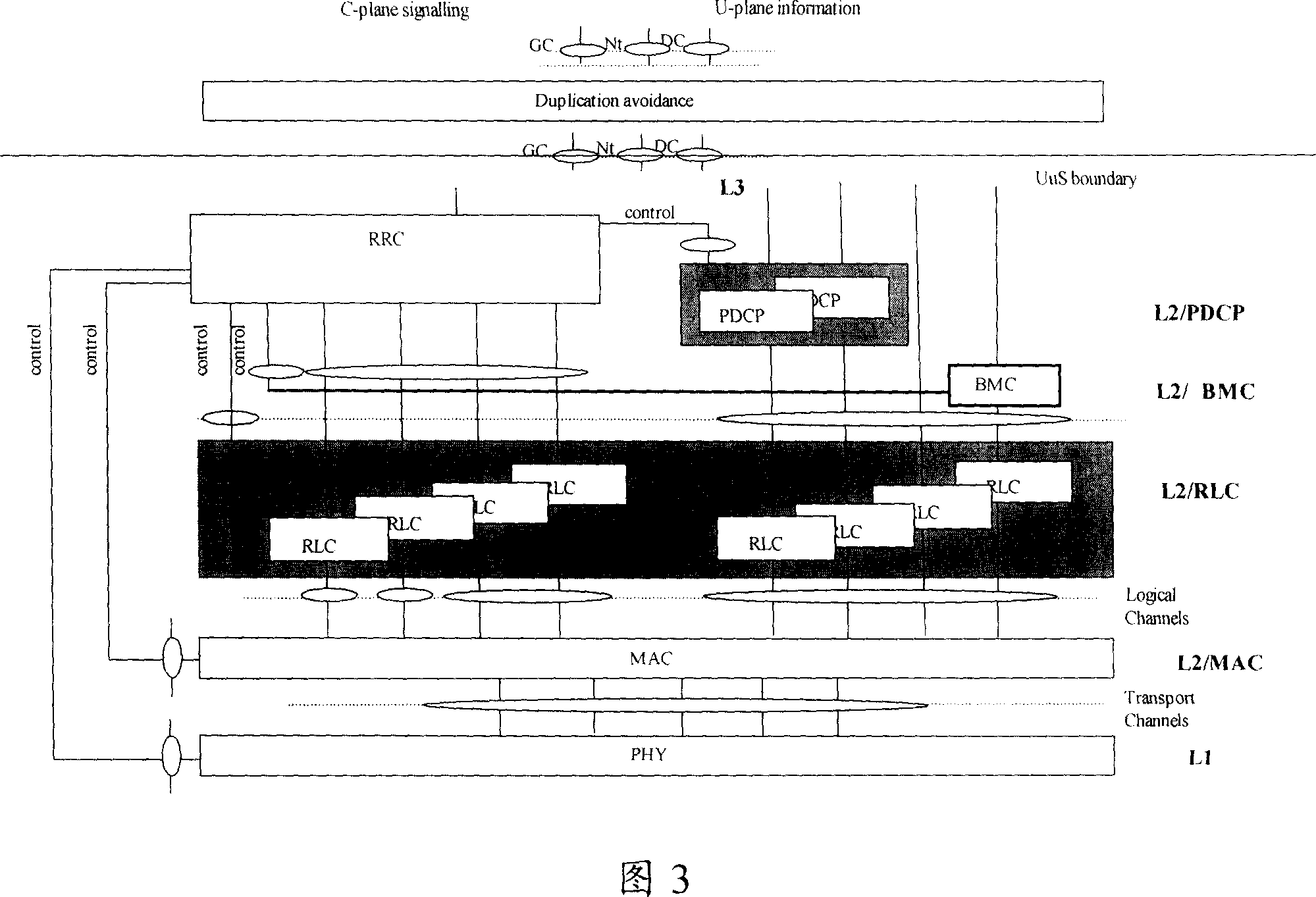
technical field [0001] The present invention relates to the communication field, in particular to a switching method and system. Background technique [0002] UMTS Universal Mobile Telecommunication Systems (UMTS Universal Mobile Telecommunication Systems) is a third-generation mobile communication system that uses the air interface of WCDMA Wide-band Code Division Multiple Access (WCDMA Wide-band Code Division Multiple Access). The UMTS system is also usually referred to as the WCDMA communication system. [0003] Functionally, the network unit can be divided into a radio access network (RAN RadioAccess Network) and a core network (CN Core Network). Among them, the wireless access network is used to handle all wireless-related functions, while the CN handles the switching and routing of all voice calls and data connections in the UMTS system and external networks. Its system structure is shown in Figure 1. [0004] The network units of the UMTS system include UE User Equi...

Claims


Application Information

Patent Timeline
Patent Type & Authority Applications(China)
IPC IPC(8): H04Q7/38H04W36/08
Inventor 郑潇潇
Owner HUAWEI TECH CO LTD
Learn More