Forming machine for concrete building unit

A molding machine and concrete technology, applied in the direction of molding indenters, etc., can solve the problems of low production efficiency, high labor intensity, poor equipment stability, etc., and achieve the effect of improving the compactness of components, increasing the strength of components, and improving the compactness.

Inactive Publication Date: 2007-07-25
周凯
View PDF1 Cites 5 Cited by
  • Summary
  • Abstract
  • Description
  • Claims
  • Application Information

AI Technical Summary

Problems solved by technology

This kind of concrete component forming machine has low automation, high labor intensity, and low production efficiency. At the same time, the existing concrete component forming machine can only use dry concrete to produce components. Because the humidity of the concrete is low, the concrete components are dense. The existing concrete component molding...

Method used


Image

  • Forming machine for concrete building unit
  • Forming machine for concrete building unit

Examples


Embodiment Construction

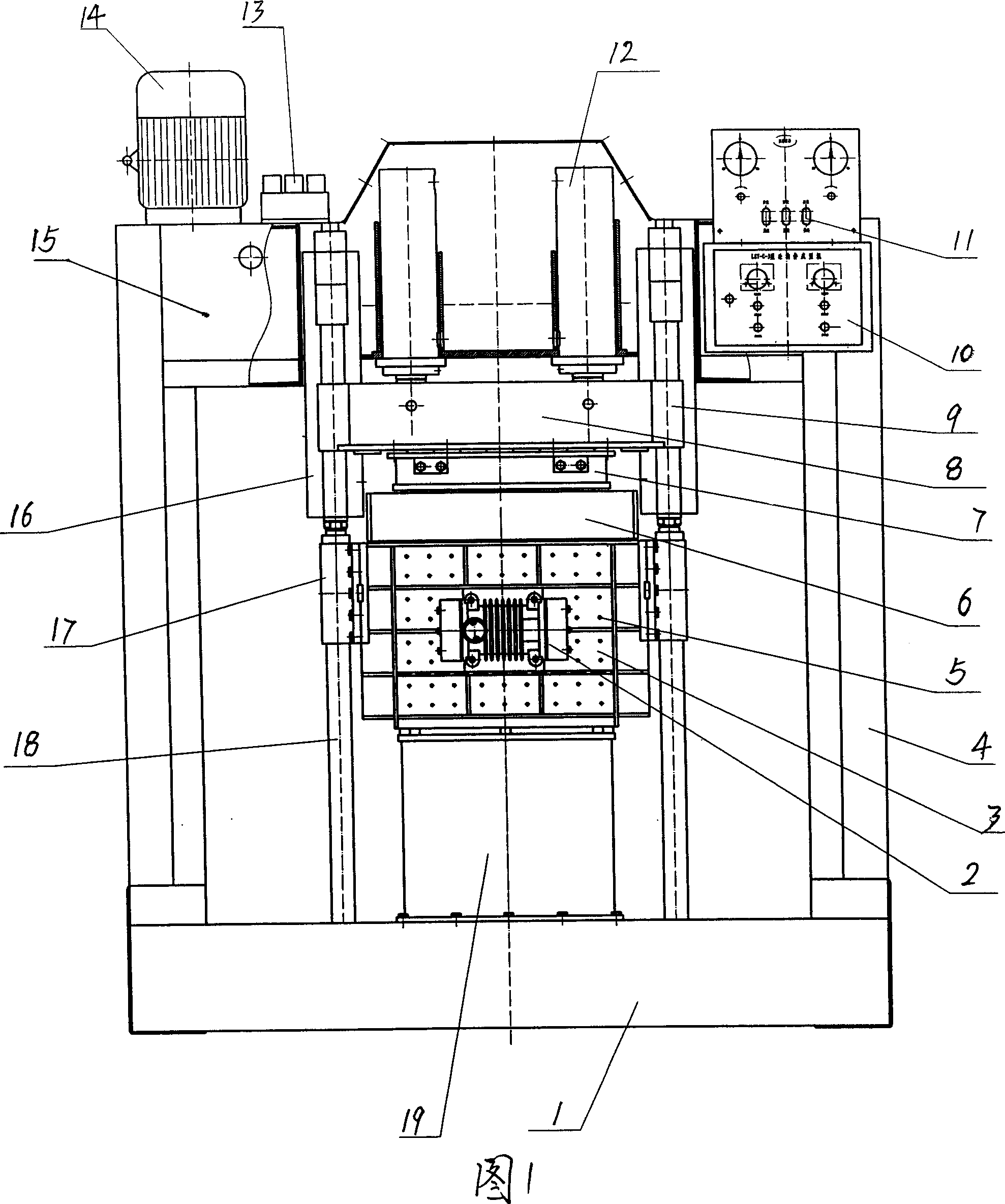
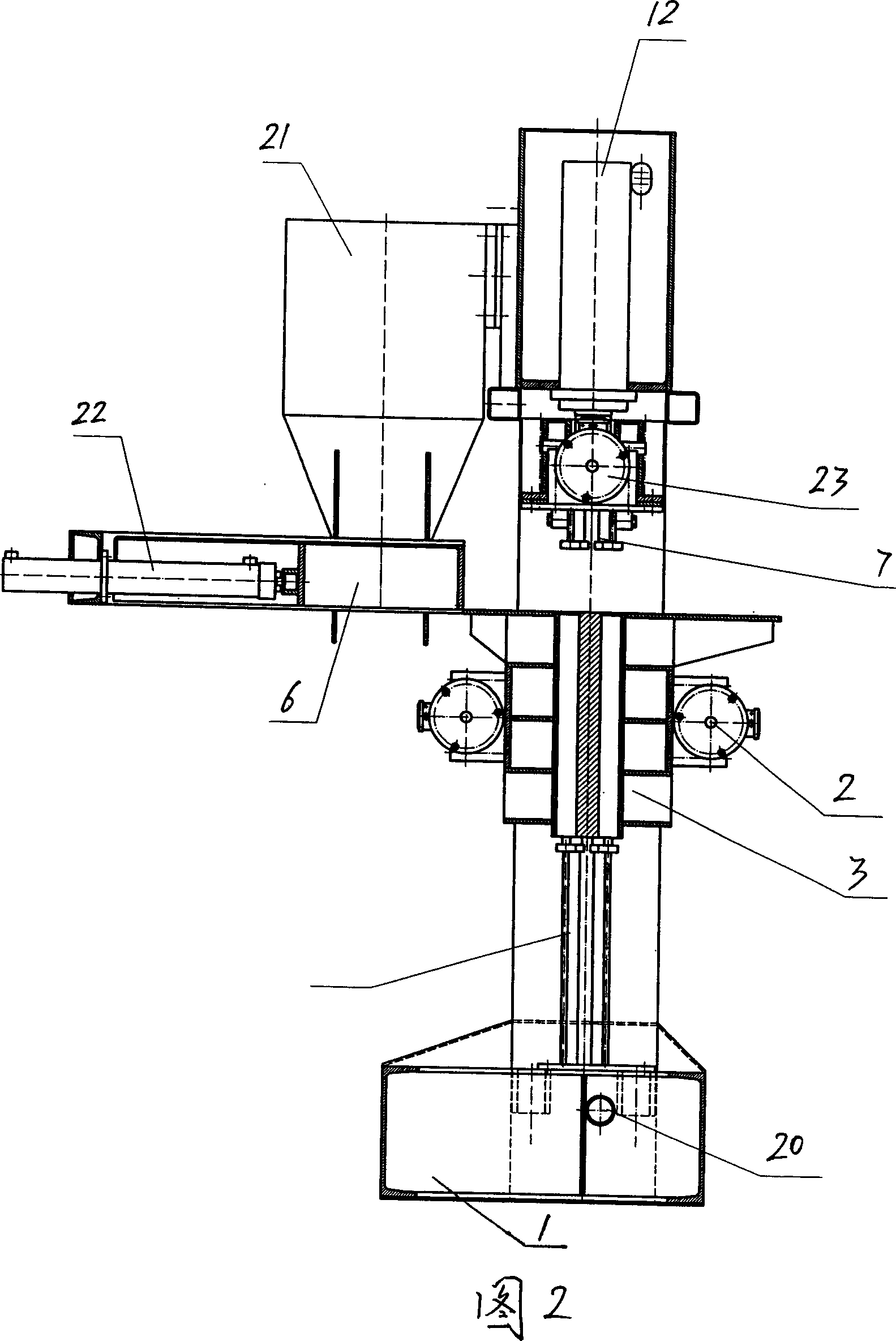
[0014] With reference to the accompanying drawings, the concrete member molding machine includes a machine base 1, side supports 4 supported on the left and right sides of the machine base 1, an upper support 15 installed on the side supports 4, and a pressure head oil cylinder 12, Hydraulic control system 13, the hydraulic control system 13 is driven by the motor 14 installed on the upper bracket 15, the electric control system box 10, the manipulation control cabinet 11 are installed in front of the upper bracket 15, and the oil drain nozzle is provided on the side of the machine base 1 20. The pressure head oil cylinder 12 is two sets arranged parallel to the left and right, so that the pressure head is evenly pressed and left and right balanced. A pressure head seat 8 is installed at the lower end of the piston rod of the pressure head oil cylinder 12, and a pair of pressure head seats 8 are arranged on the machine base 1. The component pressure bearing 19 placed, the left...


PUM


Abstract

A concrete member forming machine is composed of base, two side supporting frames, upper supporting frame, cylinder for pressing head, hydraulic control system, pressing head holder with exchangeable pressing head, concrete member bearing seat, die box, guide rods for pressing head, vibrating unit, die releasing cylinder, and automatic material supplying unit.

Description

technical field [0001] The invention relates to the technical field of producing shaped cement products by using a pressure machine. Background technique [0002] Existing concrete member forming machine has pressure head, forming mold box, mold box workbench and vibrator located on the mold box workbench or mold box. After reaching the mold box, turn on the vibrator, and after applying pressure from the pressure head, manually open the mold box, remove the molded components, and proceed to the next cycle of operation. This concrete component forming machine has low automation, high labor intensity, and low production efficiency. At the same time, the existing concrete component forming machine can only use dry concrete to produce components. Because the humidity of the concrete is low, the concrete components are dense. The degree is low; while the existing concrete component forming machine, the component demoulding method is generally horizontal demoulding or upward demo...

Claims


Application Information

Patent Timeline
IPC IPC(8): B28B3/04B28B1/087
Inventor 周凯
Owner 周凯
Why Eureka
Try Eureka