Flat plate antenna of high gain wide band

A flat-panel antenna and wide-band technology, which is applied in the direction of antenna, resonant antenna, and mid-position feed between antenna endpoints, can solve the problem of not being able to meet the electrical requirements of WiMAX broadband

Active Publication Date: 2007-07-25
UNIVERSAL GLOBAL TECH KUNSHAN
View PDF0 Cites 32 Cited by
  • Summary
  • Abstract
  • Description
  • Claims
  • Application Information

AI Technical Summary

Problems solved by technology

[0007] At present, most of the improvement of the antenna structure is to solve how to obtain good radiation efficiency and antenna gain within the operating frequency band of IEEE 802.11a / b / g. However, the above three known patents cannot meet the broadband required by WiMAX technology. Band (3.3-3.8GHz), high-gain electrical requirements, and the antenna gain of these three patents is only 1.8-2dBi

Method used


Image

  • Flat plate antenna of high gain wide band
  • Flat plate antenna of high gain wide band
  • Flat plate antenna of high gain wide band

Examples


Embodiment Construction

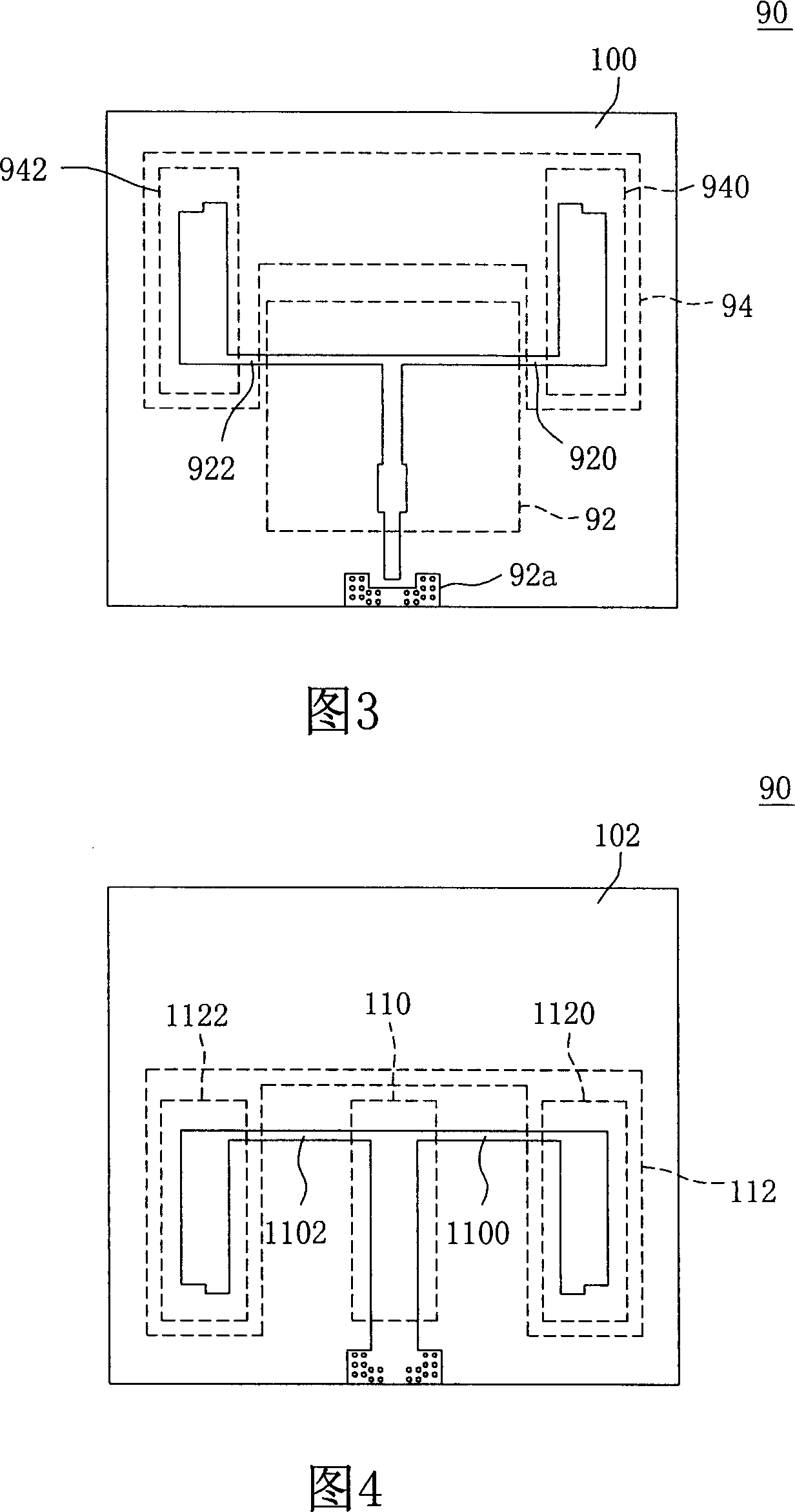
[0067] The microwave substrate of the high-gain broadband planar antenna provided by the present invention has a first surface and a second surface, and the front views of the first surface and the second surface are shown in Fig. 3 and Fig. 4 respectively.

[0068] Please refer to FIG. 3 , which is a front view of the first surface of the first embodiment of the present invention. On the first surface 100 of the microwave substrate 90, the microstrip line pattern of the circuit layer is arranged, and the first surface 100 includes the first feeding network. The unit 92 , the first symmetrical radiation unit 94 and the feed-in area 92 a, wherein the first symmetrical radiation unit 94 further includes a first radiation portion 940 and a second radiation portion 942 .

[0069] The two side arms 920 and 922 of the first feeding network unit 92 are respectively connected to the first radiating part 940 and the second radiating part 942, and the first feeding network unit 92 and th...


PUM


Abstract

The disclosed flat antenna is in use for solving issue that traditional antenna structure is unable to apply to broadband in high gain. The flat antenna includes following parts: microwave base plate with first surface and second surface; being collocated at the first surface, the first symmetrical type radiation element possesses a first radiation portion, and a second radiation portion; being collocated at the second surface, the second symmetrical type radiation element possesses a third radiation portion, and a fourth radiation portion; at least a connection unit in use for connecting the microwave base plate and reflecting plate. Design method of steps structure is adopted for tail ends of the first radiation portion, the second radiation portion, the third radiation portion, and the fourth radiation portion. The disclosed flat antenna can realize broadband in high gain.

Description

technical field [0001] The invention relates to a planar antenna structure, in particular to a planar antenna with high gain and wide frequency band. Background technique [0002] With the vigorous development of wireless communication in recent years, people's demand for bandwidth and data transmission rate of wireless communication are also increasing day by day. In the case of wireless local area network (Wi-Fi), its data transmission rate has been increased from the original 2MB and 11MB to the current 54MB, but its transmission distance is limited to within one or two hundred meters. When the transmission distance is increased to several kilometers At this time, Wi-Fi cannot meet this requirement, so the new communication technology WiMAX can be developed. WiMAX mainly regulates the communication of the wide area network, and its transmission range can reach 50 kilometers, which complies with the IEEE 802.16 standard. The communication distance of WLAN is mostly withi...

Claims


Application Information

Patent Timeline
Patent Type & Authority Applications(China)
IPC IPC(8): H01Q13/08H01Q9/16H01Q19/10H01Q1/38
Inventor 哀敬原邱利吉
Owner UNIVERSAL GLOBAL TECH KUNSHAN
Why Eureka
Try Eureka