Supercharge Your Innovation With Domain-Expert AI Agents!

Digital clock frequency multiplier

A digital clock and frequency multiplier technology, applied in the field of digital clock frequency multipliers, can solve the problems of consumption, high locking time, and the frequency of the input clock signal cannot be changed rapidly.

Inactive Publication Date: 2012-11-14
NXP USA INC
View PDF0 Cites 0 Cited by
  • Summary
  • Abstract
  • Description
  • Claims
  • Application Information

AI Technical Summary

Problems solved by technology

However, PLLs require a lot of time and design effort to ensure their stability, consume large silicon area and often require the use of external components, resulting in increased cost
Also, because the PLL has a high lock time, the frequency of the input clock signal cannot change rapidly
Furthermore, PLLs are only suitable for processing input clock signals with a limited frequency and duty cycle range, and a single PLL has a limited multiplication range

Method used


Image

  • Digital clock frequency multiplier
  • Digital clock frequency multiplier
  • Digital clock frequency multiplier

Examples


Embodiment Construction

[0013] The following detailed description, taken in conjunction with the accompanying drawings, is intended to describe presently preferred embodiments of the invention and is not intended to represent the only forms of implementing the invention. It is to be understood that the same or equivalent function may be accomplished by different embodiments which are intended to encompass the spirit and scope of the invention.

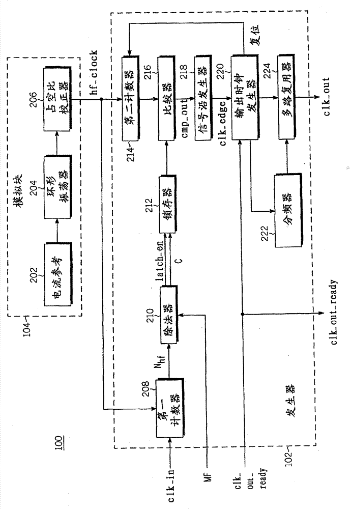
[0014] now refer to figure 1 , is a structural diagram of a digital clock frequency multiplier 100 according to an embodiment of the present invention. The digital clock multiplier 100 includes a generator 102 and an analog block 104 . with time period T clk_in The input clock signal “clk_in” of is input to the generator 102 . The generator 102 receives the input clock signal clk_in and the high-frequency digital signal "hf_clk" generated by the analog block 104, and one cycle T of the input clock signal clk_in clk_in Counting of the number of cycles of t...


PUM


Abstract

A digital clock frequency doubler (100) for increasing incoming frequency of incoming clock signal includes a generator (102) for receiving incoming clock signal and high frequency digital signal. The generator (102) generates output clock signal by using periodicity counting (Nhf) of high frequency digital signal of incoming clock signal in one cycle dividing predetermined multiplication factor (MF). The output clock signal has predetermined output frequency.

Description

technical field [0001] The present application mainly relates to a frequency generator for generating digital signals, in particular to a digital clock frequency multiplier for increasing the frequency of an input clock signal. Background technique [0002] Clock multipliers are widely used in integrated circuits. Traditionally, a phase-locked loop (PLL) has been used as a clock multiplier to increase the frequency of the input clock signal. However, the PLL requires a lot of time and design effort to ensure its stability, consumes a large silicon area and often requires the use of external components, resulting in increased cost. In addition, because the PLL has a high lock time, the frequency of the input clock signal cannot be changed rapidly. In addition, PLLs are only suitable for processing input clock signals with a limited frequency and duty cycle range, and a single PLL has a limited multiplication range. [0003] From the foregoing observations, it is desirable ...

Claims


Application Information

Patent Timeline
Patent Type & Authority Patents(China)
IPC IPC(8): H03K5/00H03L7/00G06F1/04G06F7/68
CPCG06F1/08G06F7/68
Inventor 桑杰伊·K·万德哈瓦迪亚·穆哈雷帕万·K·蒂瓦瑞
Owner NXP USA INC
Features
  • R&D
  • Intellectual Property
  • Life Sciences
  • Materials
  • Tech Scout
  • Unparalleled Data Quality
  • Higher Quality Content
  • 60% Fewer Hallucinations
Learn More