Eureka AIR delivers breakthrough ideas for toughest innovation challenges, trusted by R&D personnel around the world.

Gas radiation burner and controlling method thereof

A burner and gas technology, applied to gas fuel burners, combustion methods, burners, etc., can solve problems such as explosion and failure to guarantee the safety of burners

Inactive Publication Date: 2007-08-01
LG ELECTRONICS INC
View PDF0 Cites 0 Cited by
  • Summary
  • Abstract
  • Description
  • Claims
  • Application Information

AI Technical Summary

Problems solved by technology

In the case of refiring the burner, the gas mixture remaining in the burner body can be ignited suddenly, which can lead to an explosion
Therefore, the safety of the burner cannot be guaranteed

Method used


Image

  • Gas radiation burner and controlling method thereof
  • Gas radiation burner and controlling method thereof
  • Gas radiation burner and controlling method thereof

Examples


Embodiment Construction

[0043] Reference will now be made in detail to the preferred embodiments of the invention, examples of which are illustrated in the accompanying drawings. Wherever possible, the same reference numbers will be used throughout the drawings to refer to the same or like parts.

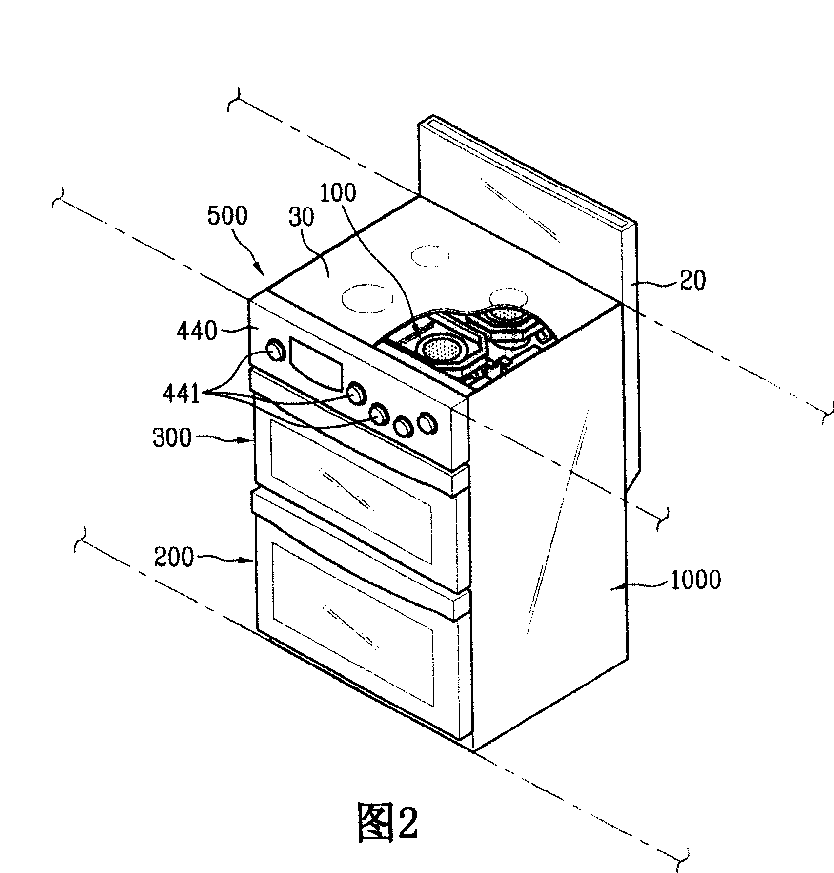
[0044] First, a gas stove or a gas range using a gas radiation burner according to an embodiment of the present invention is explained with reference to FIG. 2 . In this case, FIG. 2 shows an example of a built-in type gas stove or gas range.

[0045] Referring to FIG. 2 , a gas stove or gas range includes a body 1000 , a grill portion 200 , a grill portion 300 , and a top burner portion 500 having a plurality of gas radiant burners 100 .

[0046] The body 1000 constitutes the exterior of the gas stove or gas range. The oven part 200 is provided to a lower portion of the body 1000 and constitutes a space for cooking food by convective heat of a plurality of heaters (not shown in the drawing) provided in ...


PUM


Abstract

A gas radiation burner includes a gas supply unit for spraying a mixed gas of a gas and air; a burner body having a burner pot accommodating the mixed gas supplied by the gas supply unit and a burner housing provided on the burner pot to configure a combustion chamber; a burner mat provided over the burner pot to emit a radiant heat generated by combustion of the mixed gas supplied by the burner pot; and an air supply unit supplying air to the burner housing.

Description

[0001] Pursuant to 35 U.S.C. §119(a), this nonprovisional application claims Patent Application No. 10-2006-0006367 filed in Korea on January 20, 2006 and Patent Application No. Priority of 10-2006-0006399, the entire contents of which are hereby incorporated by reference. technical field [0002] The present invention relates to a gas radiation burner, and more particularly to a gas radiation burner and a control method thereof. While the present invention is suitable for a wide variety of applications, it is particularly suited for providing sufficient air to accelerate combustion. Background technique [0003] Generally, a gas radiant burner provided for a gas stove or a gas range is a device used for cooking by heating an object using radiant waves. In this case, the radiation waves are generated by radiators which are heated when the gas mixture is burned. The mixed gas includes gas and air. [0004] Specifically, since the glass is placed on the gas radiant burner, ...

Claims


Application Information

Patent Timeline
IPC IPC(8): F23D14/14F23D14/60F23N5/00
CPCY02B40/166F23D14/14F23D14/02F23D14/48F24C3/085F24C15/10F23D2203/007
Inventor 李大来柳廷玩梁大奉金映秀金阳昊
Owner LG ELECTRONICS INC
Why Eureka
Eureka Blog
Learn More