Energy-saving control system for the self-adapted luminescence network

An energy-saving control system and lighting network technology, applied in the field of adaptive lighting network energy-saving control system, can solve the problems of high equipment cost, single function, large energy consumption, etc., and achieve the goals of improving working efficiency, reasonable overall layout, and improving flexibility Effect

Inactive Publication Date: 2007-08-01
李超
View PDF2 Cites 38 Cited by
  • Summary
  • Abstract
  • Description
  • Claims
  • Application Information

AI Technical Summary

Problems solved by technology

[0005] The purpose of the present invention is to solve the above problems and provide an adaptive lighting network with comprehensive functions, which can smoothly adjust the working conditions of street lamps in time according to the power quality and light int

Method used


Image

  • Energy-saving control system for the self-adapted luminescence network
  • Energy-saving control system for the self-adapted luminescence network
  • Energy-saving control system for the self-adapted luminescence network

Examples


Embodiment Construction

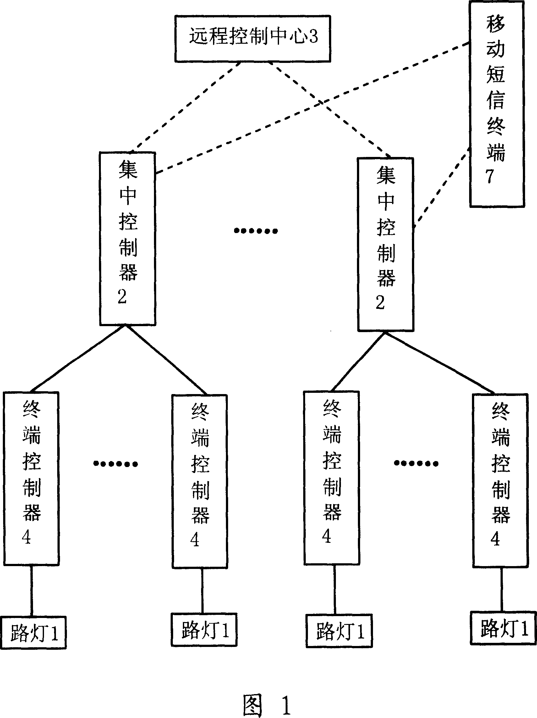
[0025] As shown in Figure 1, the self-adaptive lighting network energy-saving control system is composed of street lamp 1, remote control center 3, centralized controller 2, terminal controller 4, mobile SMS terminal 7 and so on. The street lamps 1 are connected to the power transmission line and are divided into several control areas. In each control area, there is a centralized controller 2 connected with all the street lamps 1 in the area. A terminal controller 4 is arranged between each street lamp 1 and the centralized controller 2 in each control area. The remote control center 3 can be connected with a signal input device and a monitoring screen.

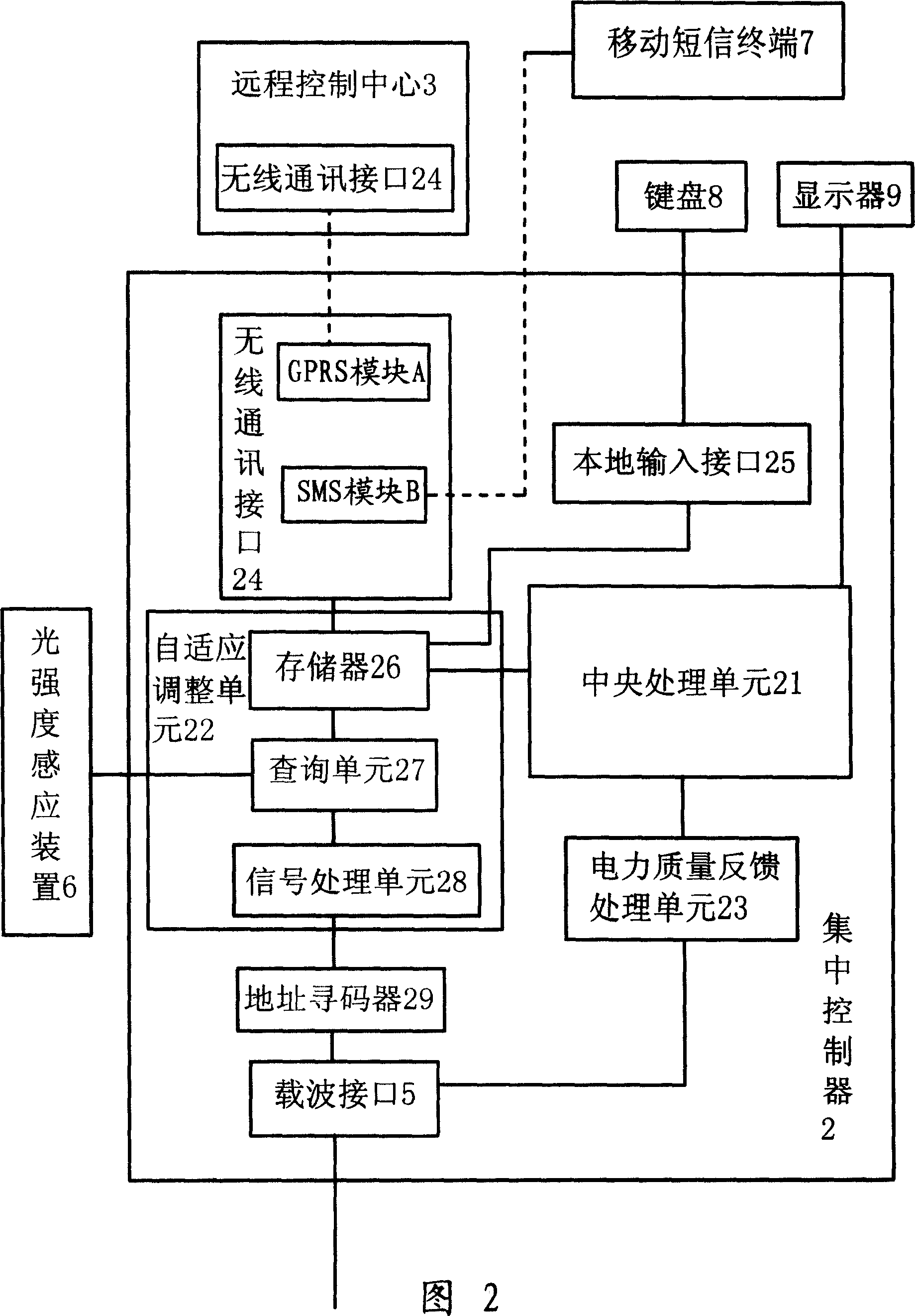
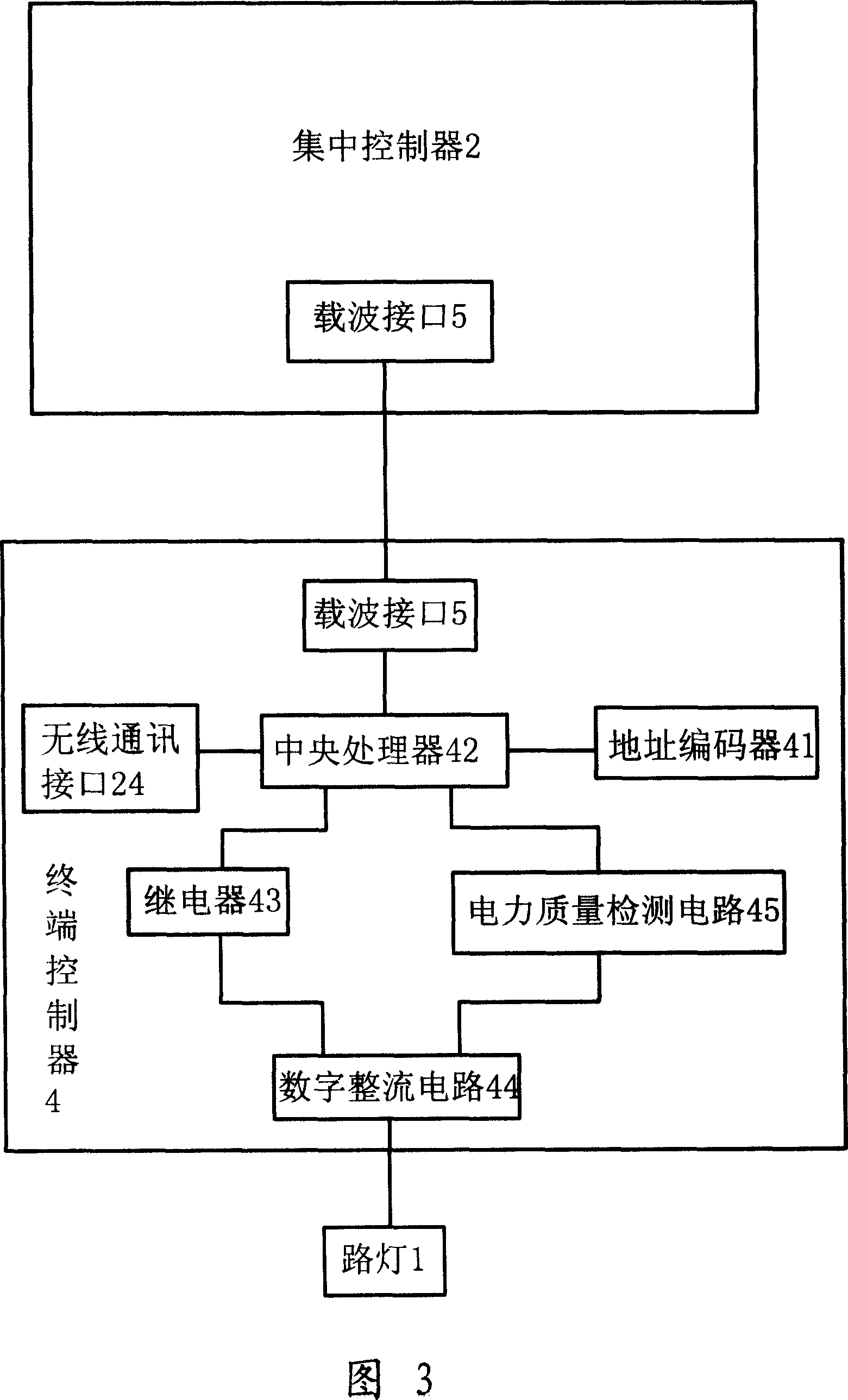
[0026]As shown in FIG. 2 , the centralized controller 2 is connected to the carrier interface 5 of the terminal controller 4 through the carrier interface 5 . Each centralized controller 2 is connected with the wireless communication interface 24 of the remote control center 3 through the wireless communication interface 24 ...


PUM


Abstract

The related adaptive control system for saving energy on lighting network applies a remote control center and every centralized controller and GPRS wireless communication to form large-area communication network, and can take local control by local access interface, wherein every centralized controller forms a small local control network with same-path terminal controller by electric-power carrier communication, while the electric quality feedback unit and adaptive adjust unit can process limp work state according to electric quality and lighting strength. This invention uses hierarchical control, can save energy efficiently, and has stable performance with low cost.

Description

technical field [0001] The invention relates to the field of lighting devices, in particular to an adaptive lighting network energy-saving control system. Background technique [0002] Currently widely used street lamps are controlled by street lamp control boxes. The control box determines the time to turn on and turn off the lights, and when the time comes, all street lights are turned on or off. The disadvantage is that the flexibility of the system is very poor, there is only one time to turn on and off the lights; the setting is troublesome, and it is necessary to go to each street light control box to actually set it up, the workload is heavy, and the work efficiency is low. It cannot be controlled by a single point to achieve energy saving, and turning off the lights in a block will seriously affect the sight of pedestrians and vehicles. In addition, when the brightness of the surrounding environment changes due to weather changes or the voltage changes under condit...

Claims


Application Information

Patent Timeline
IPC IPC(8): H05B37/02H04Q9/00
CPCY02B20/42Y02B60/50Y02B20/40
Inventor 李超郝婕孙新江任平俊梁越
Owner 李超
Why Eureka
Try Eureka