Turbine nozzle support device and steam turbine

A turbine nozzle and supporting device technology, applied in the field of steam turbines, can solve the problems of increased cost of steam turbines, steam leakage, inability to maintain fastening force, etc., and achieve the effect of improving the internal efficiency of the turbine and reducing leakage

Inactive Publication Date: 2007-08-01
KK TOSHIBA
View PDF1 Cites 12 Cited by
  • Summary
  • Abstract
  • Description
  • Claims
  • Application Information

AI Technical Summary

Problems solved by technology

Therefore, with long-term operation, the fastening bolts gradually undergo so-called creep deformation, and cannot maintain the fastening force at the initial stage of operation. As a result, steam leakage may occur.
[0013] In addition, when the number of turbine nozzles 53 supported by one turbine nozzle support device 57 increases, since its axial length also becomes longer, the turbine nozzle support device 57 itself will not The deformation of thermal expansion caused by the temperature distribution of the cylinder, the pressure distribution of the steam passing through the stage 55, the number of fastening bolts, etc. are complicatedly intertwined, and it is difficult to obtain a uniform fastening force on the joint surface of the cylinder 56 as a whole, and the tiny steam cannot be avoided. to leak
[0014] As a countermeasure to avoid the leakage as described above, it is conceivable to increase the diameter of the fastening bolt or to increase the area of ​​the joint (joint flange) portion of the cylindrical body 56, etc., but both will increase the size of the turbine nozzle support device 57, and the turbine housing The volume of 51 will inevitably increase, which will lead to problems such as increased cost and securing the installation area of ​​the steam turbine.
[0015] Also, since the cylindrical body 56 securely fixes only the joint (joint flange) portion by a plurality of fastening bolts, for example, deformation due to internal pressure and thermal expansion may concentrate on other weak cylindrical portions.
However, this non-uniform deformation makes the seal fins provided at the base of the turbine casing 51, the seal fins provided between the turbine nozzle 53 and the turbine rotor 52, or the seal fins provided at the tip of the turbine moving blade 54 and the turbine The gap between the sealing blades etc. between the nozzle holders 57 changes, and friction (contact) occurs when the gap is narrowed, so that the operation has to be stopped. On the contrary, when the gap is widened, the steam leakage increases, which becomes a factor of lowering the internal efficiency of the turbine.
[0016] In this way, there is a reduction in efficiency inside the turbine due to steam leakage accompanying the deformation of the turbine nozzle holder. Conversely, when the prevention of steam leakage is strengthened, the fastening bolts are enlarged, which in turn leads to an increase in the size of the turbine housing that joins the turbine nozzle holder. question

Method used


Image

  • Turbine nozzle support device and steam turbine
  • Turbine nozzle support device and steam turbine
  • Turbine nozzle support device and steam turbine

Examples


Embodiment Construction

[0044] Hereinafter, embodiments of a turbine nozzle support device and a steam turbine according to one embodiment of the present invention will be described with reference to the drawings and the symbols of the drawings.

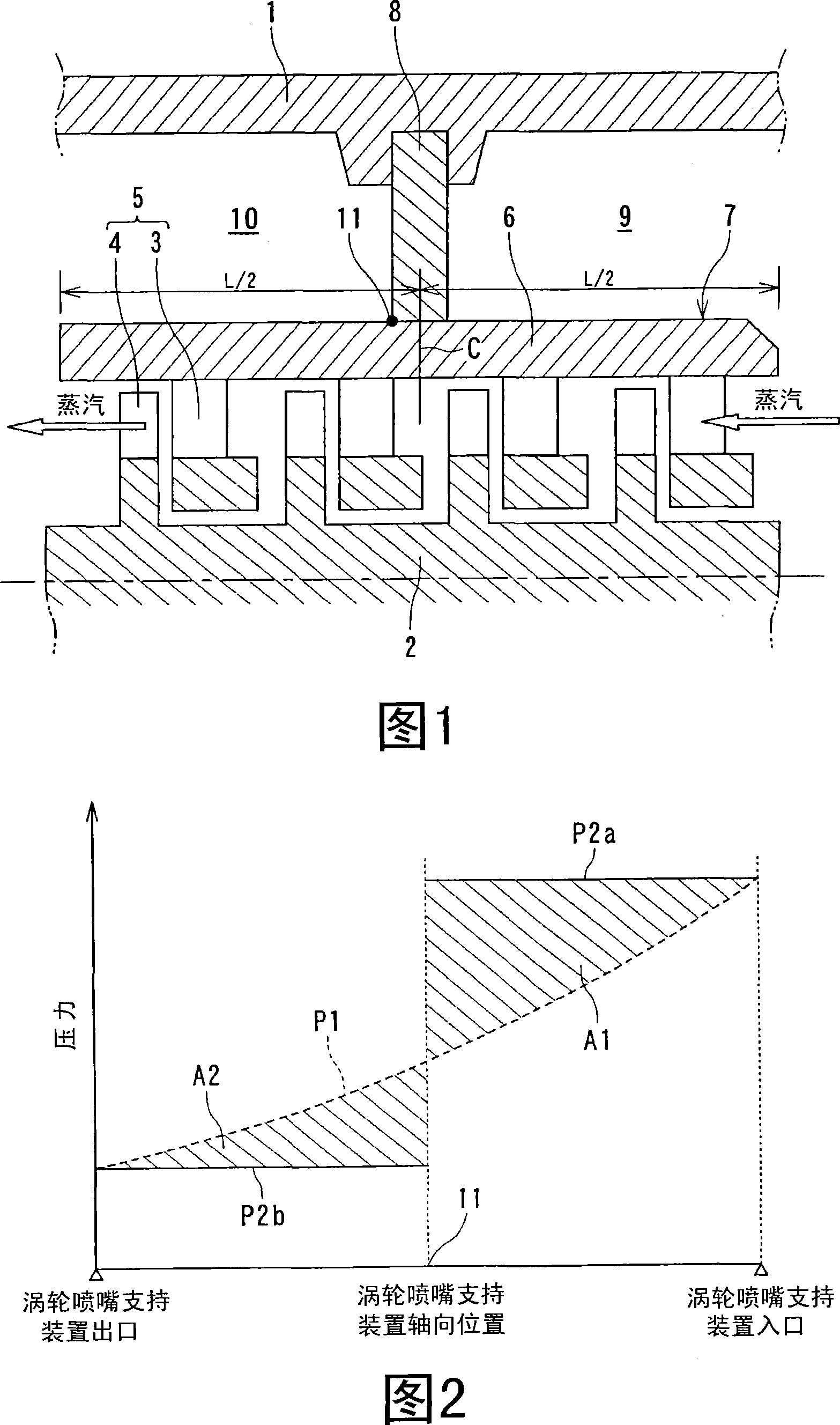
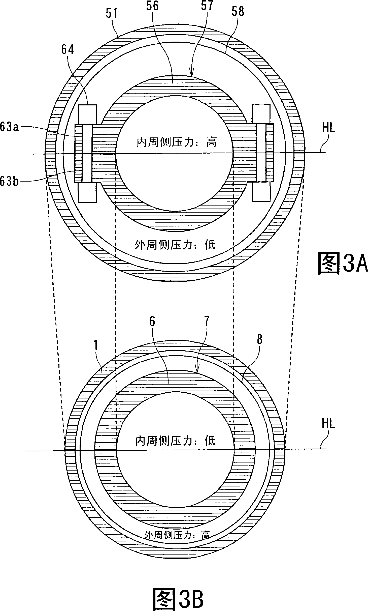
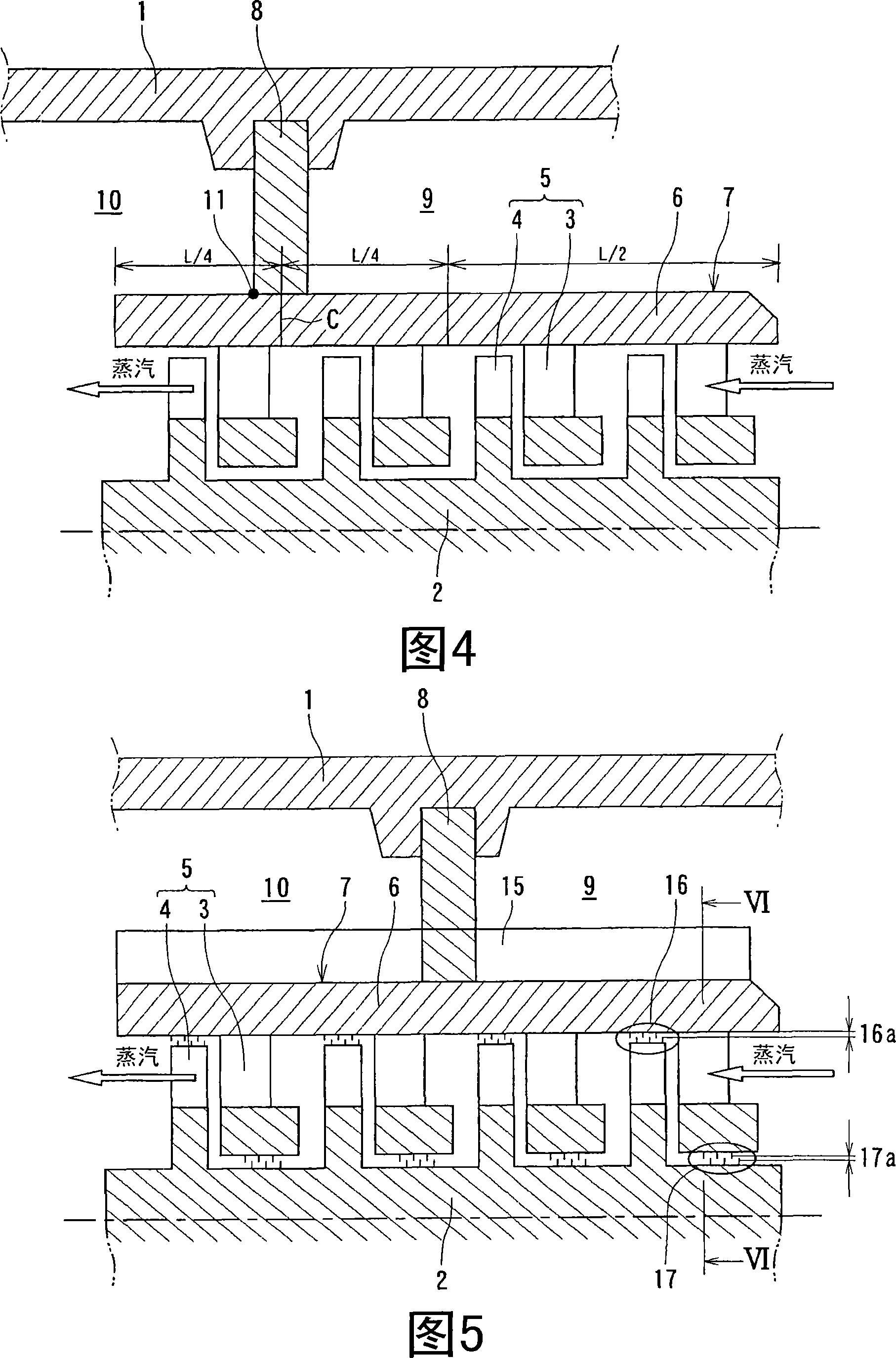
[0045] FIG. 13 is a schematic cross-sectional view in the longitudinal direction of the steam turbine according to this embodiment. A steam turbine typically has pressure zones for a high-pressure turbine, an intermediate-pressure turbine, and a low-pressure turbine. Fig. 13 shows the high-pressure turbine and the medium-pressure turbine among them. As shown in FIG. 13 , the high-pressure turbine and the medium-pressure turbine in each pressure zone of the aforementioned steam turbine are integrally arranged in one turbine housing 1 . Each of the high-pressure turbine and the intermediate-pressure turbine includes turbine rotor blades 3 fitted in the circumferential direction of the turbine rotor (rotating shaft) 2 , and turbine rotor blades 3 that are pai...


PUM


Abstract

A turbine nozzle support device of a steam turbine, comprising a plurality of turbine stages and a cylindrical body. Each of the turbine stages further comprises a turbine casing, turbine moving blades implanted in the circumferential direction of a turbine rotor in the turbine casing, and turbine nozzles forming pairs with the moving blades and disposed on the upstream side of the moving blades along the circumferential direction of the turbine rotor. The cylindrical body further comprises a plurality of turbine nozzles formed roughly concentrically to the turbine casing and fixedly axially engaged with the inner part of the turbine casing. The turbine nozzle support device also comprises a separating plate for fixing. The outer peripheral part of the separating plate is fixed to the turbine casing and the outer peripheral part of the cylindrical body is fixed to the inner peripheral part thereof. The separating plate for fixing shields an atmosphere on the upstream side from the atmosphere on the downstream side of the separating plate, and the installation position of the separating plate is set on the downstream side of the axial center position of the cylindrical body.

Description

technical field [0001] The present invention relates to a turbine nozzle (stator vane) support device of a steam turbine and a steam turbine having the support device, in particular to a structure of a turbine nozzle support device which supports a plurality of turbine nozzles and fixes a turbine casing. Background technique [0002] The steam turbine has a turbine stage (turbine stage), and the turbine stage includes: a turbine moving blade embedded in the circumferential direction of a turbine rotor (rotary shaft) provided in a turbine housing; Turbine nozzles (stator blades) arranged in the circumferential direction, and the steam turbine have a structure having a plurality of turbine stages. [0003] Among them, the turbine nozzle (stationary vane) is sandwiched between the nozzle diaphragm inner ring and the diaphragm outer ring, and is fixed inside the casing by supporting the nozzle diaphragm outer ring with the turbine casing. [0004] Furthermore, a structure in wh...

Claims


Application Information

Patent Timeline
Patent Type & Authority Applications(China)
IPC IPC(8): F01D25/24F01D9/02
CPCF01D25/24F01D25/26F01D25/246F05D2220/31F05B2230/606F01D9/02F01D11/025F05D2230/642
Inventor 川上宏
Owner KK TOSHIBA
Why Eureka
Try Eureka