
Machine tool

A technology for machine tools and components, applied in the field of machine tools, can solve problems such as adhesion to operators and leakage of coolant, and achieve the effects of easy maintenance, fewer parts, and fewer assembly processes

Active Publication Date: 2007-08-08
BROTHER KOGYO KK
View PDF1 Cites 5 Cited by
  • Summary
  • Abstract
  • Description
  • Claims
  • Application Information

AI Technical Summary

Problems solved by technology

Coolant, etc. may leak from the gap between the linear guide rail and the rollers that constitute the opening and closing mechanism of the slide door, and may adhere to the operator

Method used


Image

  • Machine tool
  • Machine tool
  • Machine tool

Examples


Embodiment Construction

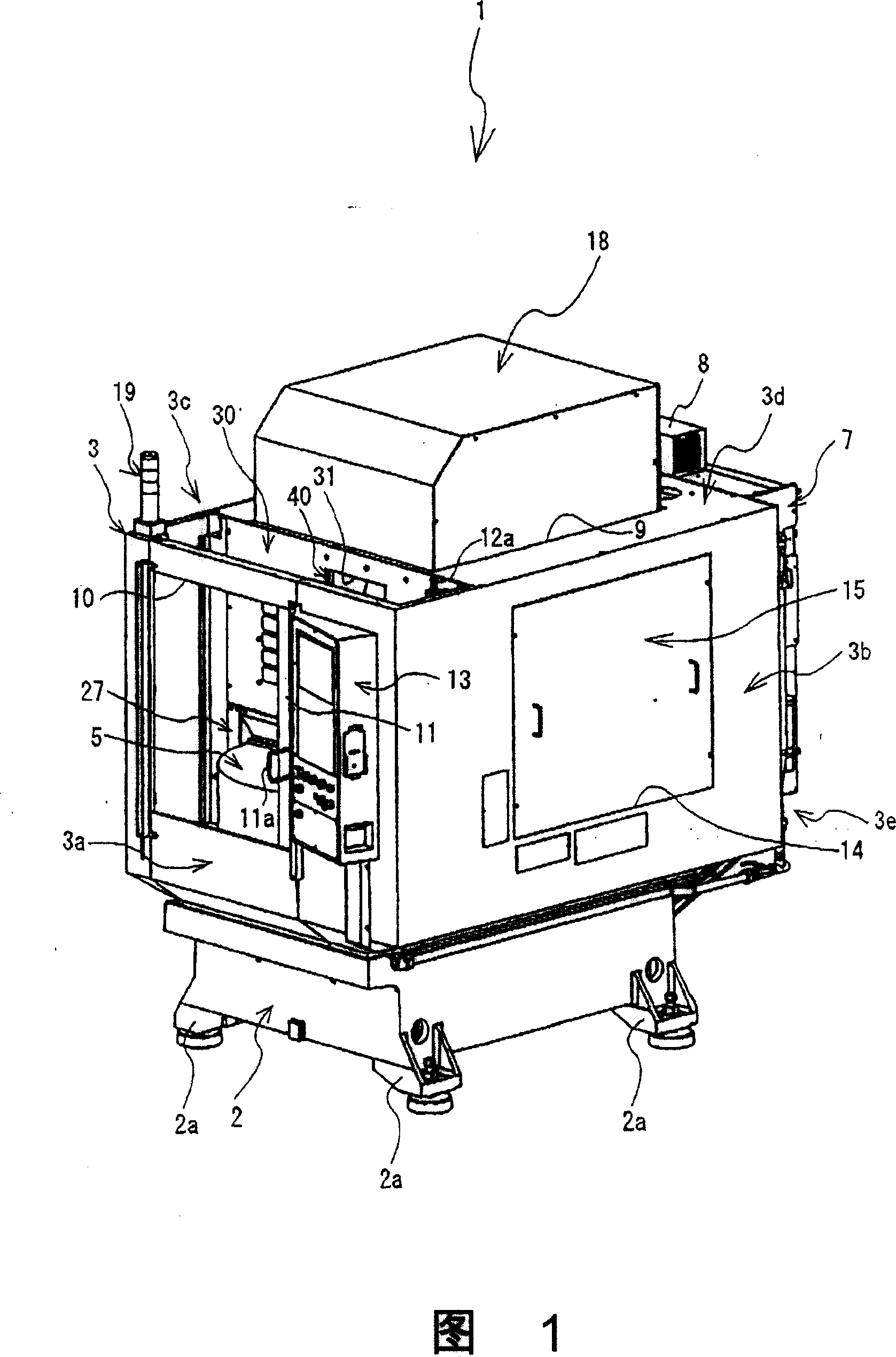
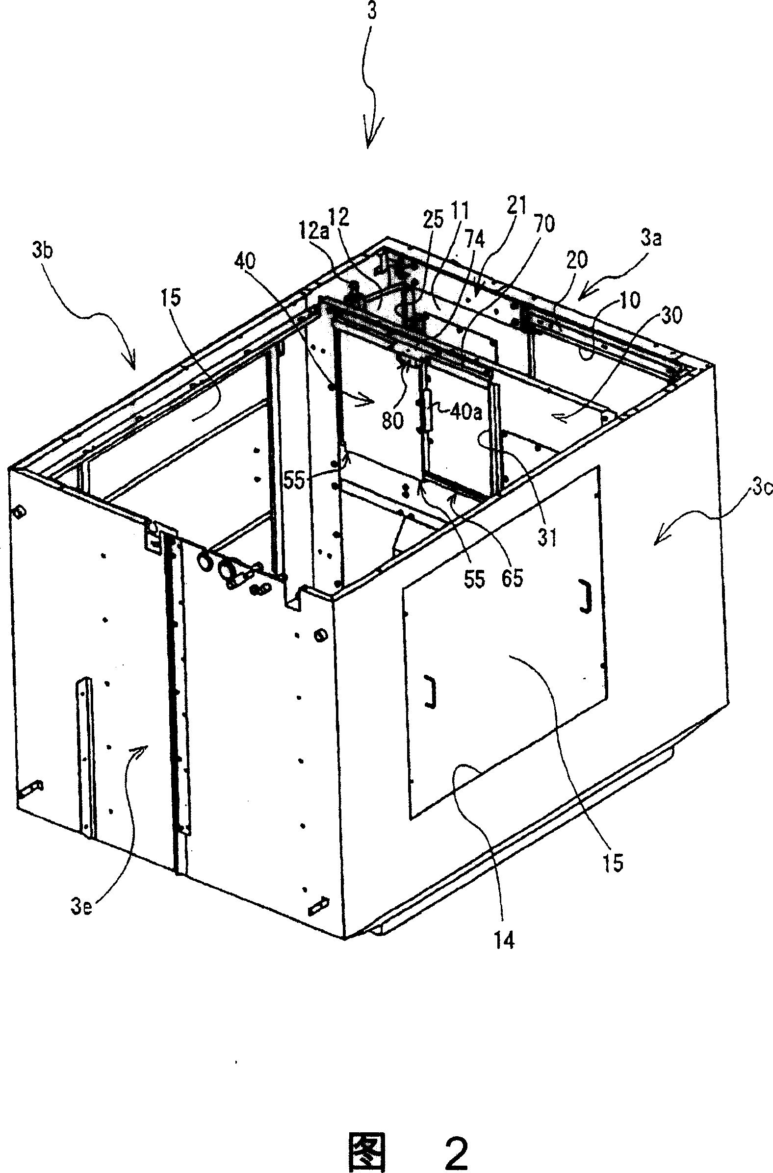
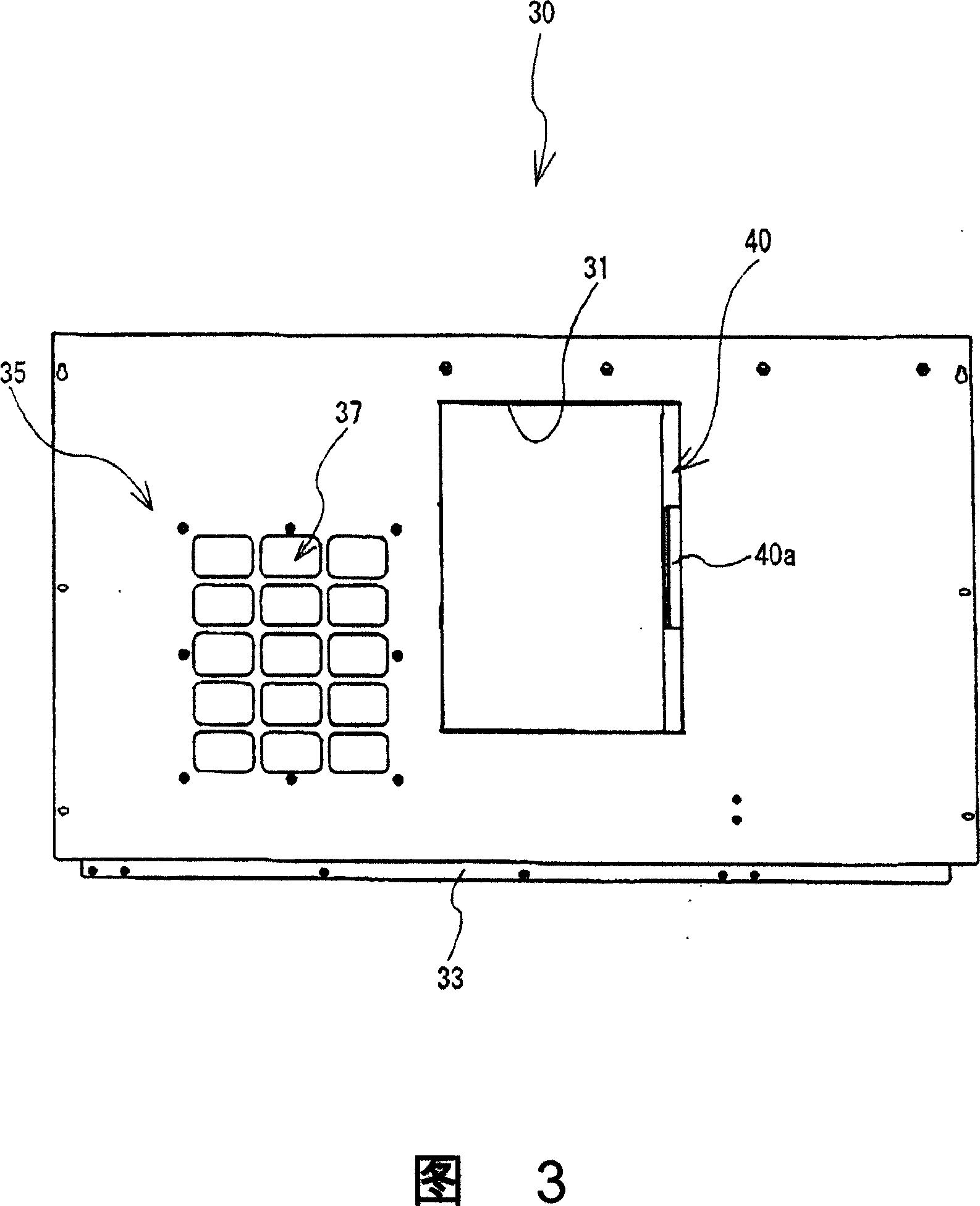
[0029] As shown in FIG. 1 , the machining center 1 of this embodiment has a partition 30 for partitioning the machining area inside the protective shutter 3 . The partition plate 30 is provided with a slide door 40 for opening and closing the opening 31 . The first feature of the present invention is that the number of parts can be reduced by simplifying the structure of the guide rail that guides the sliding door 40 . The second feature of the present invention is that by covering the guide rail structure with the guide rail cover plate 70 , it is possible to prevent chip powder scattered from the processing area from adhering to and accumulating in the guide rail structure.

[0030] Next, a schematic configuration of the machining center 1 will be described. The machining center 1 shown in FIG. 1 can implement the required machining (such as "boring", "milling", "drilling", "cutting", etc.) ) machine tools. The main body of the machining center 1 comprises: a base 2 made ...


PUM


Abstract

A processing center is equipped with a partition board (30) at inner side of a protecting baffle plate. A sliding door (40) set at peristome (31) of the partition board (30) hitches its superior side hitching extensible guide to the superior side extensible guide (60) of the peristome (31). Then, the sliding door (40) moves by driving the superior side hitching extensible guide to shift at the superior side extensible guide (60). Furthermore, since the lower side hitching extensible guide (55) of the sliding door (4) is held by the lower side extensible guide (65) of the peristome (31) and the partition board (30), the pendulum motion of the lower end is restricted when the sliding door (40) moves. Since the extensible guide cover board (70) covers the superior side hitching extensible guide and the superior side extensible guide (60), the borings powder is prevented from piling up at the superior side extensible guide (60).

Description

technical field [0001] The present invention relates to a machine tool, in particular to a machine tool having a door for opening and closing an opening in a cover wall. Background technique [0002] Conventionally, in a machining center which is a type of machine tool, a machine tool body for machining a workpiece (workpiece) using a cutting tool is provided on a base, that is, a base. A protective baffle covering part or all of the machine tool body is provided on the base. This protective shield prevents chip powder or coolant (cutting fluid) scattered from the rotary table and machine body arranged on the upper part of the base from scattering to the outside. [0003] An opening through which workpieces on the rotary table enter and exit is provided on the front surface of the protective baffle. A pair of opening and closing doors which can be opened and closed are provided in this opening part. Linear guide rails for moving the opening and closing door are provided i...

Claims


Application Information

Patent Timeline
Patent Type & Authority Applications(China)
IPC IPC(8): B23Q11/08E05D15/06H01H21/34
CPCB23Q11/08B23Q11/0825B23Q11/0891F16P3/00
Inventor 村井友浩
Owner BROTHER KOGYO KK
Learn More