Axial-flow windwheel

An axial-flow wind and hub technology, which is applied to the components of pumping devices for elastic fluids, non-variable-capacity pumps, machines/engines, etc. It takes away the heat of the outdoor unit and does not consider reducing the separation of the boundary layer, so as to achieve the effects of low rotor weight and rotor production cost, reduced wake strength, low noise and motor load

Inactive Publication Date: 2007-08-08
GD MIDEA AIR-CONDITIONING EQUIP CO LTD
View PDF0 Cites 17 Cited by
  • Summary
  • Abstract
  • Description
  • Claims
  • Application Information

AI Technical Summary

Problems solved by technology

Because the air volume is sensitive to the change of load, the air volume of the conventional 2-blade axial-flow wind wheel is about 30% lower than that of the conventional 3-blade or 4-blade wind wheel, which is not conducive to quickly taking away the heat of the outdoor unit; if the ordinary 3-blade or 4-blade is used Although the axial flow fan can well solve the problem of insufficient flow rate and static pressure rise of the two-bladed axial flow wind wheel, the increase in the number of blades will lead to an increase in its own weight, an increase in the motor load, and the cost of the wind wheel will also increase. The increase of weight increases by more than 30% to 50%
[0004] In addition, in a conventional axial-flow wind turbine, on two or more blades integrally formed around the hub (hub), the corner formed by the rear edge of the blade and the outer edge end of the blade forms a flat surface in the downstream direction of the airflow. No consideration is given to suppressing noise and improving flow by reducing boundary layer separation and reducing rotor wake, nor is it considered to reduce noise, nor is it considered by improving the blade trailing edge, blade middle and top regions. Treatment to reduce rotor weight and motor load

Method used


Image

  • Axial-flow windwheel
  • Axial-flow windwheel
  • Axial-flow windwheel

Examples


Embodiment Construction

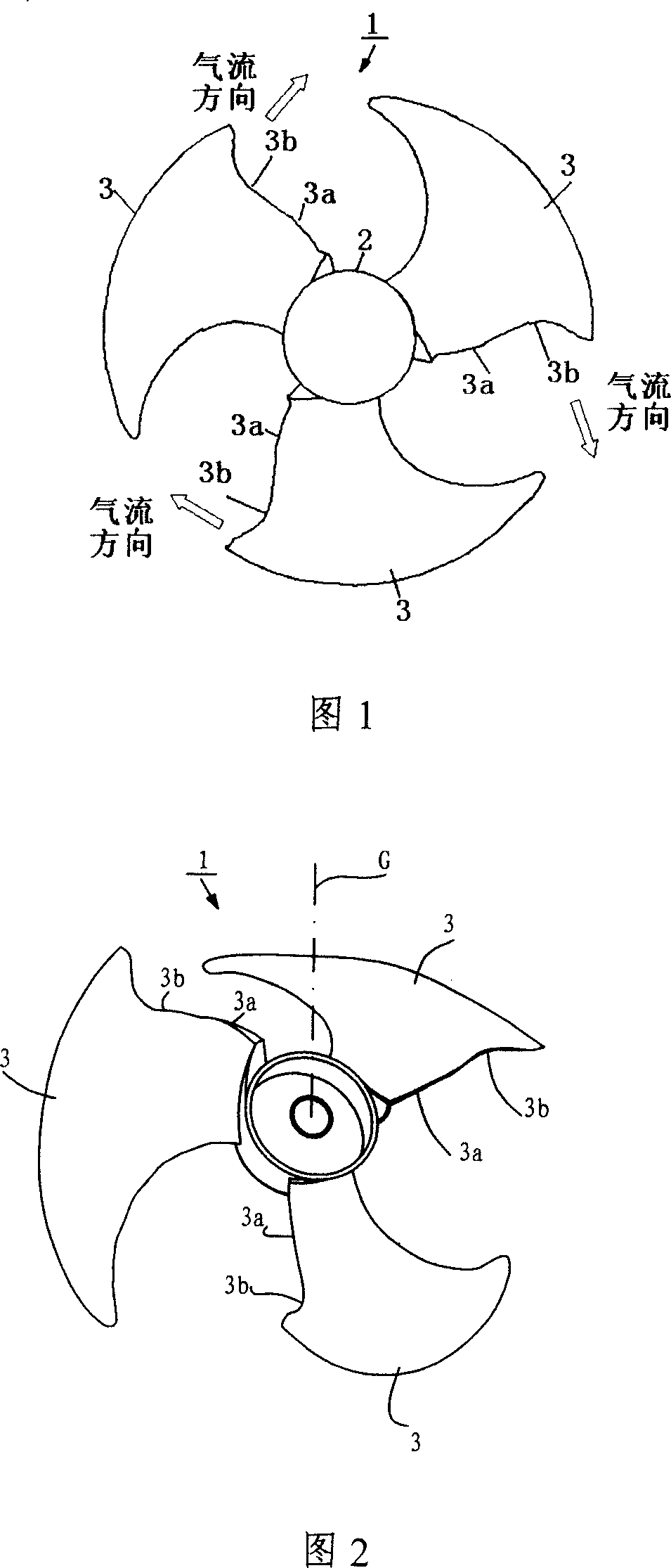
[0025] The present invention will be further described below with reference to the drawings and embodiments.

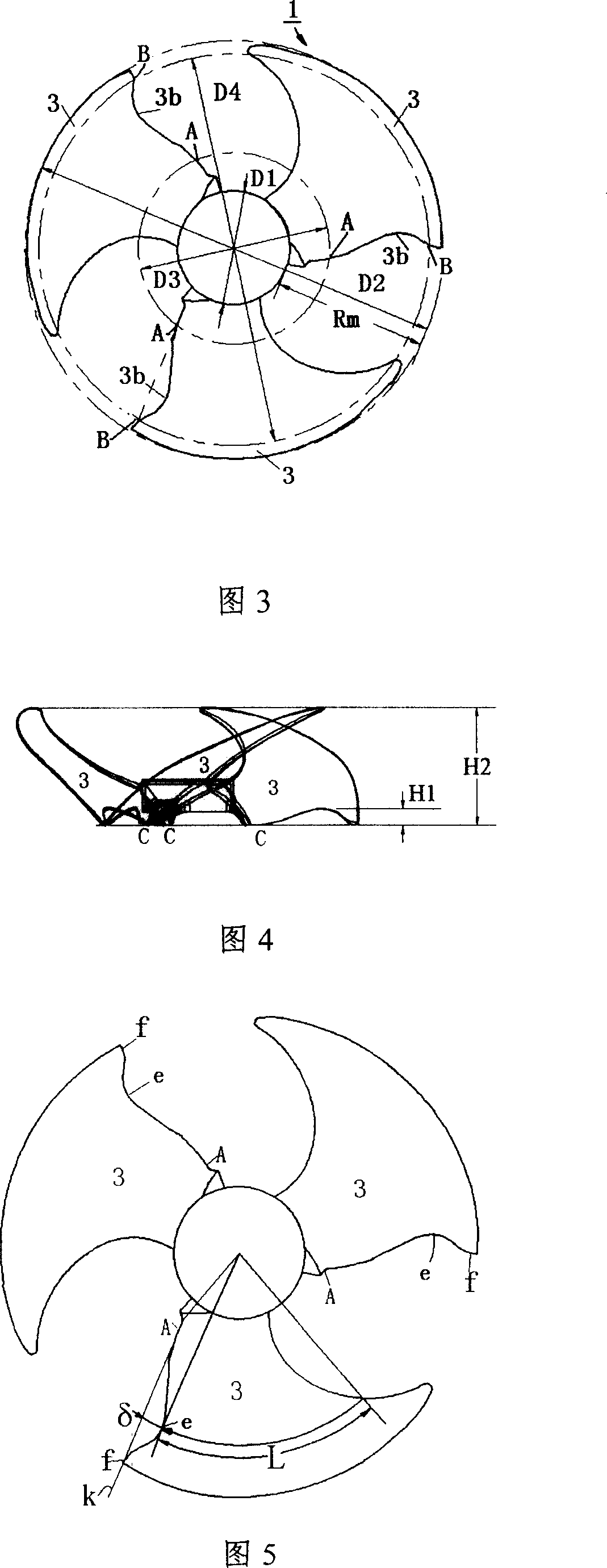
[0026] In the figure, 1 is the axial flow wheel, 2 is the hub, 3 is the blade, 3a is the downstream edge of the airflow, 3b is the recessed part, D1 is the diameter of the hub, D2 is the outer diameter of the axial flow wheel, and D3 is the blade The diameter of the circumference of the starting position A of the trailing edge of the blade, D4 ​​is the diameter of the circumference of the position B where the trailing edge of the blade ends, Rm is the height of the blade, H1 is the maximum height of the recessed part from the lowest position C of the trailing edge of the blade 3, H2 Is the height of the wind turbine blade calculated from the lowest position C of the trailing edge of the blade 3, δ is the depth of the depression, L is the length of the chord line of the blade, f is the tip trailing edge point, k is the connection line, 11 is the outdoor air-conditioning un...


PUM


Abstract

An axial-flow wind wheel comprises three blades set on a hub, wherein, the end area of the blades is dishing toward to the costal air-in direction; the three blades use the rotary central axis of the wind wheel as center each other and they allocate equal-spaced or unequal-spaced in the 120degree+-15degree. The external diameter of the axial-flow is defined as D2, the hub diameter is defined as D1, the height of the blade Rm is defined as (D2-D1) / 2, the circumference diameter in which there is the beginning dishing place A is defined as D3, (D3-D1) / 2=(0.10-0.47)Rm. Since the high-middle part of the trailing edge change the distribution of pressure of the blades before the blade root part, the high pressure draught compartment of the blades flow direction low pressure surface advanced to make local pressure ascending, to reduce boundary layer separating, to make the boundary layer turn into turbulent flow before getting the front of the blade end, to reduce convolution noise and rotor wake, thereby having low noise and big air quantity.

Description

Technical field [0001] The invention relates to an axial flow wind wheel, in particular to a three-blade axial flow wind wheel suitable for an outdoor unit of an air conditioner. Background technique [0002] Axial fans are mostly used in outdoor units of air conditioners. In the conventional axial flow fan, the rear edge in contact with the downstream side of the outlet airflow (hereinafter, the rear edge of the blade in contact with the downstream side of the airflow is referred to as the "blade trailing edge") is convex or flat in the downstream direction of the airflow outlet. Form 2 to 4 leaves together. [0003] A single blade in a conventional axial flow wind wheel with two blades has a heavy load, each blade works under high load, the flow and static pressure are relatively low, the wind noise is high, and the motor is required to have a higher speed. The requirements for the strength and motor load characteristics of the 2-blade axial flow wind wheel are relatively high....

Claims


Application Information

Patent Timeline
IPC IPC(8): F04D29/38
Inventor 游斌伍光辉程志明向运明
Owner GD MIDEA AIR-CONDITIONING EQUIP CO LTD
Why Eureka
Try Eureka