Flat plated three-phase linear permanent-magnet synchronous motor

A technology of permanent magnet synchronous motor and flat plate, which is applied in the direction of electrical components, electromechanical devices, electric components, etc. It can solve the problems of difficult design, complicated winding insulation, long winding ends, etc., and achieve simple manufacturing process, improved performance, and end-to-end short effect

Inactive Publication Date: 2011-05-11
HARBIN INST OF TECH
View PDF4 Cites 3 Cited by
  • Summary
  • Abstract
  • Description
  • Claims
  • Application Information

AI Technical Summary

Problems solved by technology

[0003] In order to solve the tooth pitch τ of the existing flat three-phase linear permanent magnet synchronous motor t and polar distance τ p The design is not easy to take into account, the ends of the windings of each phase cross each other, the ends of the windings are long, the copper loss is large, the insulation of the windings is complicated, and the manufacturing cost is high. The present invention designs a flat three-phase linear permanent magnet synchronous motor.

Method used


Image

  • Flat plated three-phase linear permanent-magnet synchronous motor
  • Flat plated three-phase linear permanent-magnet synchronous motor
  • Flat plated three-phase linear permanent-magnet synchronous motor

Examples


specific Embodiment approach 1

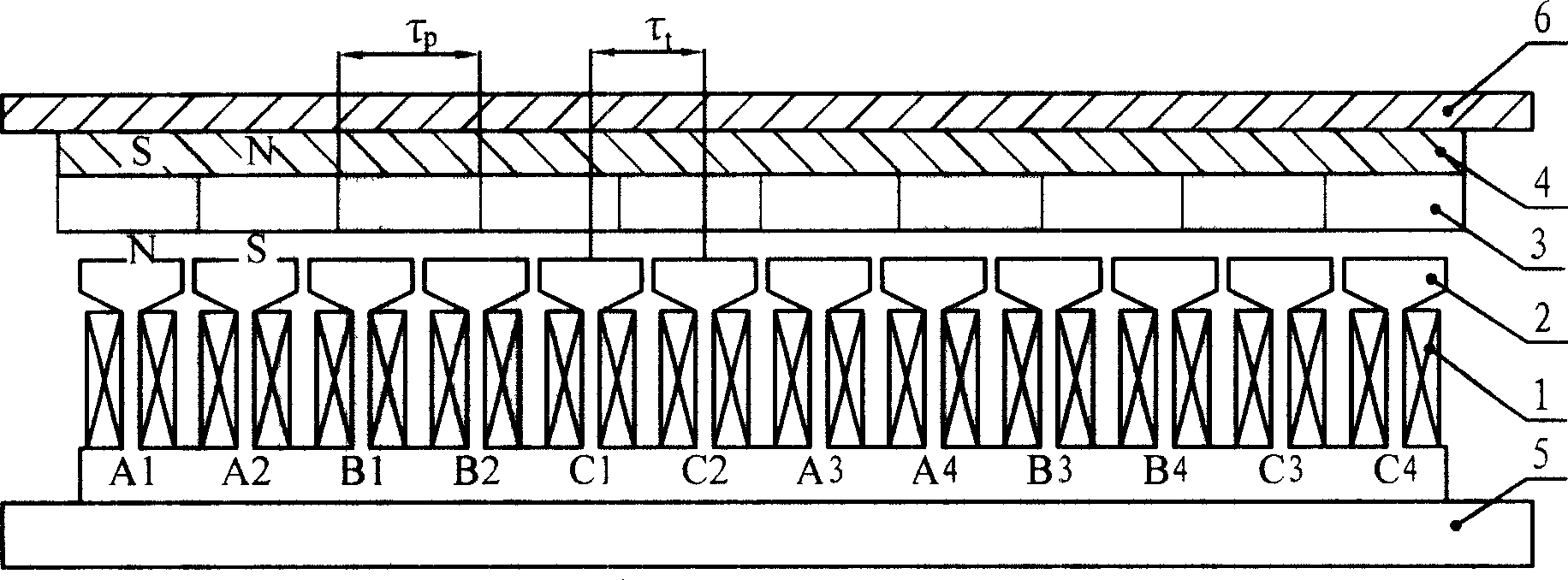
[0013] Specific implementation mode one: see figure 1 This embodiment will be described. The flat three-phase linear permanent magnet synchronous motor of this embodiment is composed of a casing 6, an armature component and a permanent magnet excitation component, an air gap is left between the permanent magnet excitation component and the armature component, and the permanent The magnet excitation part is composed of a permanent magnet 3 and a permanent magnet yoke 4, the armature part is composed of an armature winding 1 and an armature core 2, and the permanent magnet yoke 4 is fixed on the inner surface of the casing 6, so The permanent magnets 3 are fixed on the inner surface of the permanent magnet yoke 4, the permanent magnets 3 are magnetized in parallel, the magnetization direction is perpendicular to the direction of motion, and the magnetization directions of every two adjacent permanent magnets 3 are opposite, and the armature components It is a movable part, and...

specific Embodiment approach 2

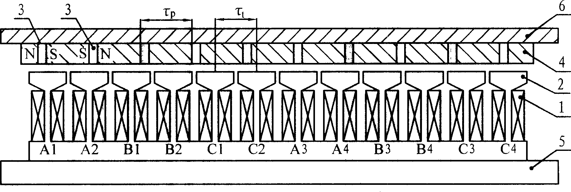
[0014] Specific implementation mode two: see figure 2 This embodiment will be described. The difference between the flat three-phase linear permanent magnet synchronous motor of this embodiment and the first embodiment is that the permanent magnet 3 is embedded in the permanent magnet yoke 4 and arranged at intervals with the permanent magnet yoke 4, and the permanent magnet 3 Parallel magnetization, the magnetization direction is parallel to the moving direction, and the magnetization directions of every two adjacent permanent magnets 3 are opposite.

specific Embodiment approach 3

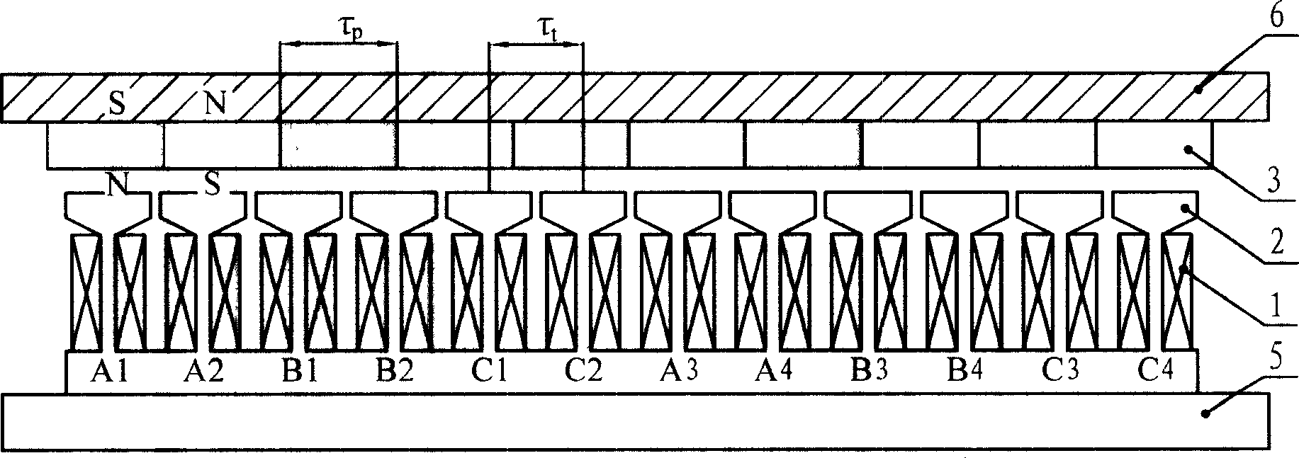
[0015] Specific implementation mode three: see image 3 This embodiment will be described. The flat three-phase linear permanent magnet synchronous motor of the present embodiment includes a casing 6, an armature component and a permanent magnet excitation component, an air gap is left between the permanent magnet excitation component and the armature component, and the casing 6 is made of magnetically conductive material, the permanent magnet excitation part is composed of a permanent magnet 3, the permanent magnet 3 is fixed on the inner surface of the casing 6, the permanent magnet 3 is magnetized in parallel, and the magnetization direction is perpendicular to the moving direction, The magnetization directions of every two adjacent permanent magnets 3 are opposite, and the armature part is a movable part, and the armature part is composed of the armature winding 1 and the armature core 2, and the armature core 2 and the output part 5 are fixed The side of the armature cor...


PUM


Abstract

The invention relates to a flat plated three-phase linear permanent-magnet synchronous motor, belonging to the motor field. The invention overcomes the problems in the prior flat plated three-phase linear permanent-magnet synchronous motor that the designs of a pitch tau t and a polar distance tau p are not easy considerate, the winding end parts are long and mutual cross, the insulation of the windings is complex, and the production cost is high and so on. The flat plated three-phase linear permanent-magnet synchronous motor comprises an armature part and a permanent-magnet excitation part, wherein, these two parts have gas gap therebetween; the armature part is composed of an armature winding and an armature iron core; the permanent excitation part is composed of a permanent-magnet part and a permanent-magnet yoke; the armature iron core pitch tau t and the permanent-magnet polar distance tau p satisfy the following formula as 3ntau t=(3n+-1)tau p, wherein n is a natural number. The invention not only can be used as the linear motor with high performance, but also can be used as the linear generator with high performance, thereby having wide application prospect.

Description

technical field [0001] The invention relates to the field of motors, in particular to a flat three-phase linear permanent magnet synchronous motor. Background technique [0002] The armature core pitch τ of the traditional flat three-phase linear permanent magnet synchronous motor t The pole distance τ from the permanent magnet p Satisfy the relation 3τ t =τ p , this structure is called an integer slot structure, that is, the number of slots per pole and phase of the motor is an integer. The main problem of the linear permanent magnet synchronous motor with an integer slot structure is: on the one hand, the positioning force of the motor caused by the cogging effect is relatively large ; On the other hand, the performance-to-volume ratio of the motor is low, which is mainly due to the fact that when the pole distance τ of the motor p When the design is large, the yoke part of the permanent magnet will be thickened, which will increase the volume and weight of the motor, ...

Claims


Application Information

Patent Timeline
Patent Type & Authority Patents(China)
IPC IPC(8): H02K41/03
Inventor 寇宝泉李立毅
Owner HARBIN INST OF TECH
Why Eureka
Try Eureka