Blow-moulding method and device

A blow molding equipment and blow molding technology, applied in the field of blow molding equipment, can solve problems such as increased failure rate, large space occupation, and difficult design

Inactive Publication Date: 2007-08-15
DONG GUAN FOUNDER MASCH CO LTD
View PDF0 Cites 15 Cited by
  • Summary
  • Abstract
  • Description
  • Claims
  • Application Information

AI Technical Summary

Problems solved by technology

In this way, since a temporary storage position relay station is required for hot blanks, it takes up a lot of space and the mechanism is complicated
Moreover, the raw material has to be taken and delivered multiple times, which reduces the efficiency of the whole equipment and increases the failure rate, especially for the mechanism design of the blown container with a large mouth.

Method used


Image

  • Blow-moulding method and device
  • Blow-moulding method and device
  • Blow-moulding method and device

Examples


Embodiment Construction

[0052] The specific embodiments of the method and equipment of the present invention will be described in further detail below in conjunction with the accompanying drawings.

[0053]Fig. 1 is an overall structural diagram of the blow molding equipment of the present invention. As shown in the figure, the equipment includes a preform loading device 100 , a heating device 200 , a preform removal device 300 and a blowing device 400 installed on the fuselage 9 . The preform feeding device 100 transports the preforms to the heating device 200 for heating, and the preform taking device 300 takes out the preforms that have been heated from the heating device 200 and transports them to the blowing device 400, and the blowing device 400 transfers the preforms transported by the preform taking device 300 Perform blow molding.

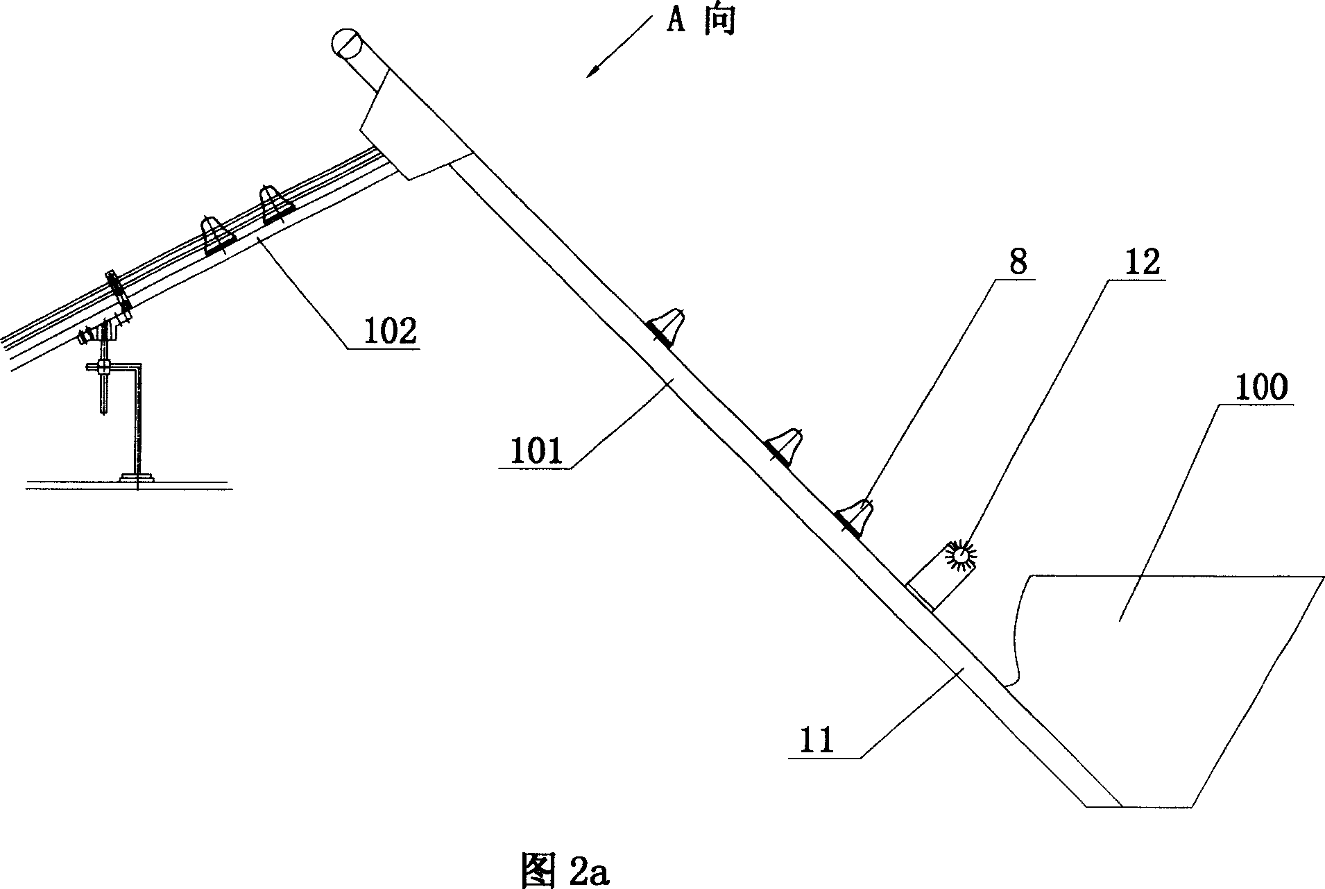
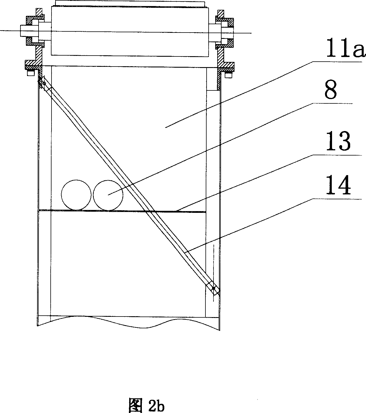
[0054] Fig. 2a is a schematic diagram of the embryo feeding device of the blow molding equipment of the present invention, and Fig. 2b is a schematic diagram of...


PUM


Abstract

The invention provides a method for blowing and shaping plastic and relative plastic blowing machine. The method comprises that 1, in blank feeder, the feeder furnishes and arranges material blanks, while the opening of the blank is downward and fed into a heater, 2, in the heater, the heater uniformly heats the material blank to reduce the opening temperature lower than blank temperature, and feeds the blank into a blank taker, 3, feeds the heated blank into a blower, 4, in the blower, the heated blank one-way intermits and feeds, while each time can blow at least one blank into a container, 5, blows the container outside the plastic blower. The invention can produce the container with large opening, with high efficiency and effect.

Description

technical field [0001] The invention relates to a blow molding method and blow molding equipment, in particular to a blow molding equipment suitable for blowing blanks with relatively large openings. Background technique [0002] With the development of society, blow molding technology is also developing, and the blanks are constantly showing their diversity. Many manufacturers are in urgent need of fully automatic blanking technology, so as to improve production efficiency and improve the working environment of operators. At present, the preform loading device commonly used in blow molding equipment slides in the guide rail with the mouth of the preform facing down. Therefore, the preform needs to be turned over by the manipulator before being sent out for heating, and the structure is relatively complicated. If the mouth of the blank is large, it will be more difficult for the manipulator to grab, the success rate will be reduced, and more cylinder accessories will be need...

Claims


Application Information

Patent Timeline
Patent Type & Authority Applications(China)
IPC IPC(8): B29C49/64B29C49/78B29C49/42B29C49/28B29C49/58
Inventor 李伟宏
Owner DONG GUAN FOUNDER MASCH CO LTD
Why Eureka
Try Eureka