Totally-enclosed large differential pressure open-close glasses valve

A large pressure difference, fully enclosed technology, applied in the field of valves and valves, can solve problems such as inability to operate under pressure, achieve smooth lateral transposition, achieve smooth opening and closing, and reduce procurement costs

Inactive Publication Date: 2007-08-15
邢建栋
View PDF0 Cites 2 Cited by
  • Summary
  • Abstract
  • Description
  • Claims
  • Application Information

AI Technical Summary

Problems solved by technology

Although the fully enclosed horizontal glasses valve does not have the problem of gas leakage, it also cannot be operated under pressure.

Method used


Image

  • Totally-enclosed large differential pressure open-close glasses valve
  • Totally-enclosed large differential pressure open-close glasses valve
  • Totally-enclosed large differential pressure open-close glasses valve

Examples


Embodiment 1

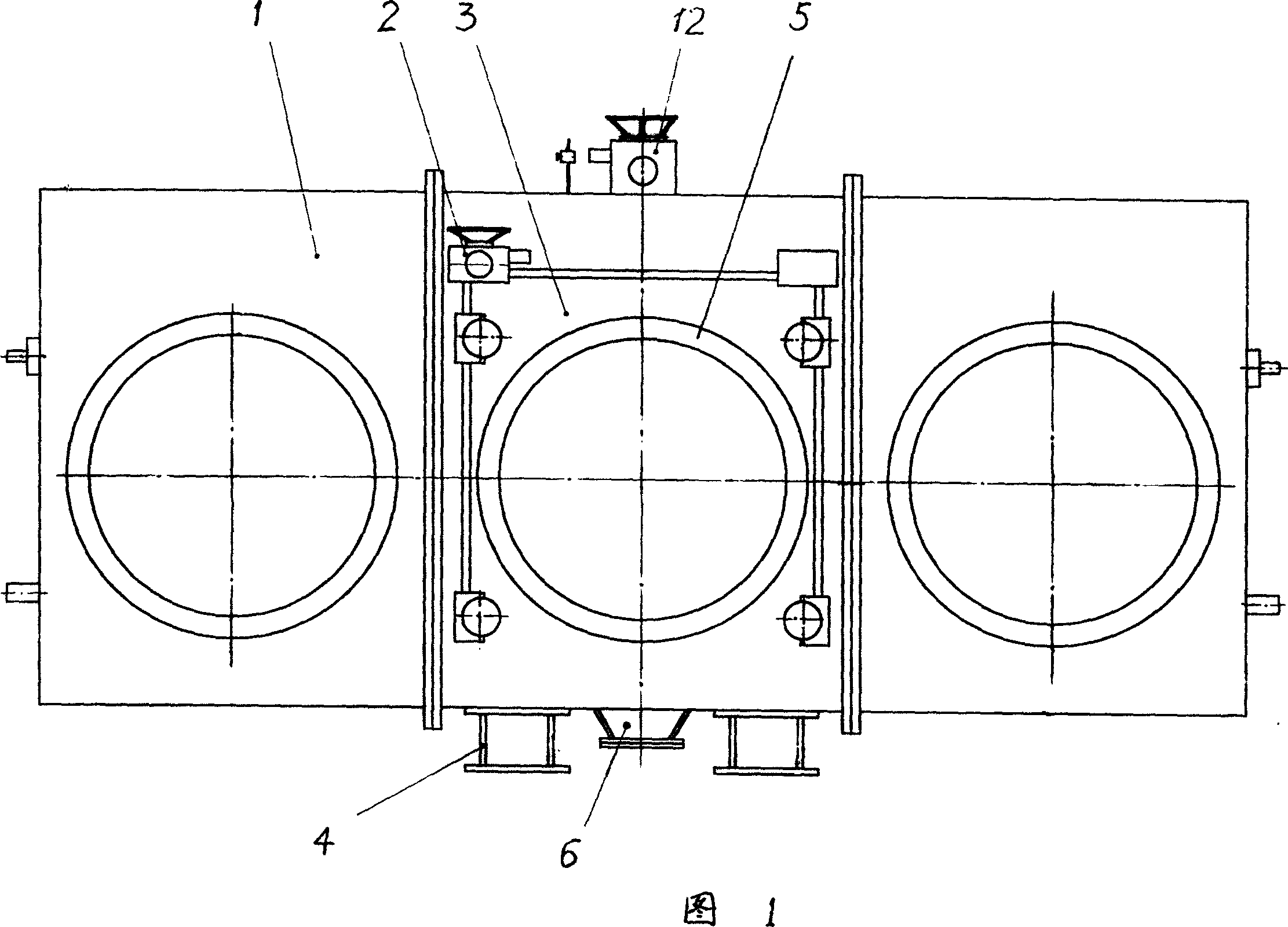
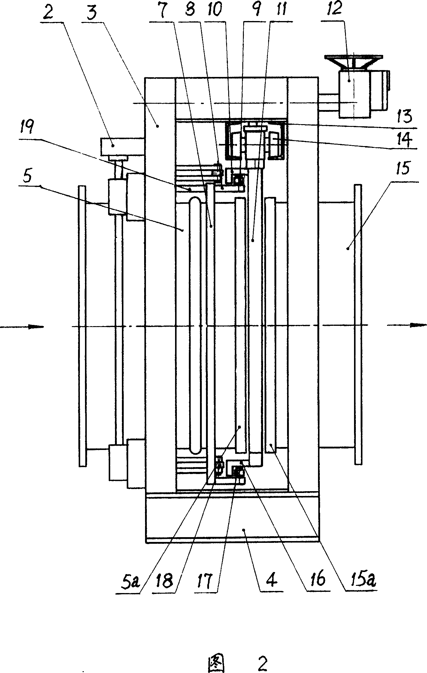
[0021] As shown in the figure, the overall structure of the spectacle valve of the present invention basically adopts the structural form of the existing fully enclosed horizontal spectacle valve, that is, a fixed valve body 15 and a movable valve body 5 with bellows are connected at the front and rear ends of the main valve box 3 (Fig. 2), respectively seal and connect an auxiliary valve box 1 (Fig. 1) on both sides of the main valve box 3, the bottom surface of the main valve box 3 is connected with a base 4, and is provided with an ash outlet 6; A valve plate 11 (Fig. 2) is clamped between the valve seat 15a of 15 and the valve seat 5a of the movable valve body 5. A valve plate compression and release mechanism is installed on the main valve box and the movable valve body, a valve plate transposition and lateral movement mechanism is installed on the top surface of the main valve box and the valve plate, and a valve plate pressure bearing is installed in the main valve box 3...

Embodiment 2

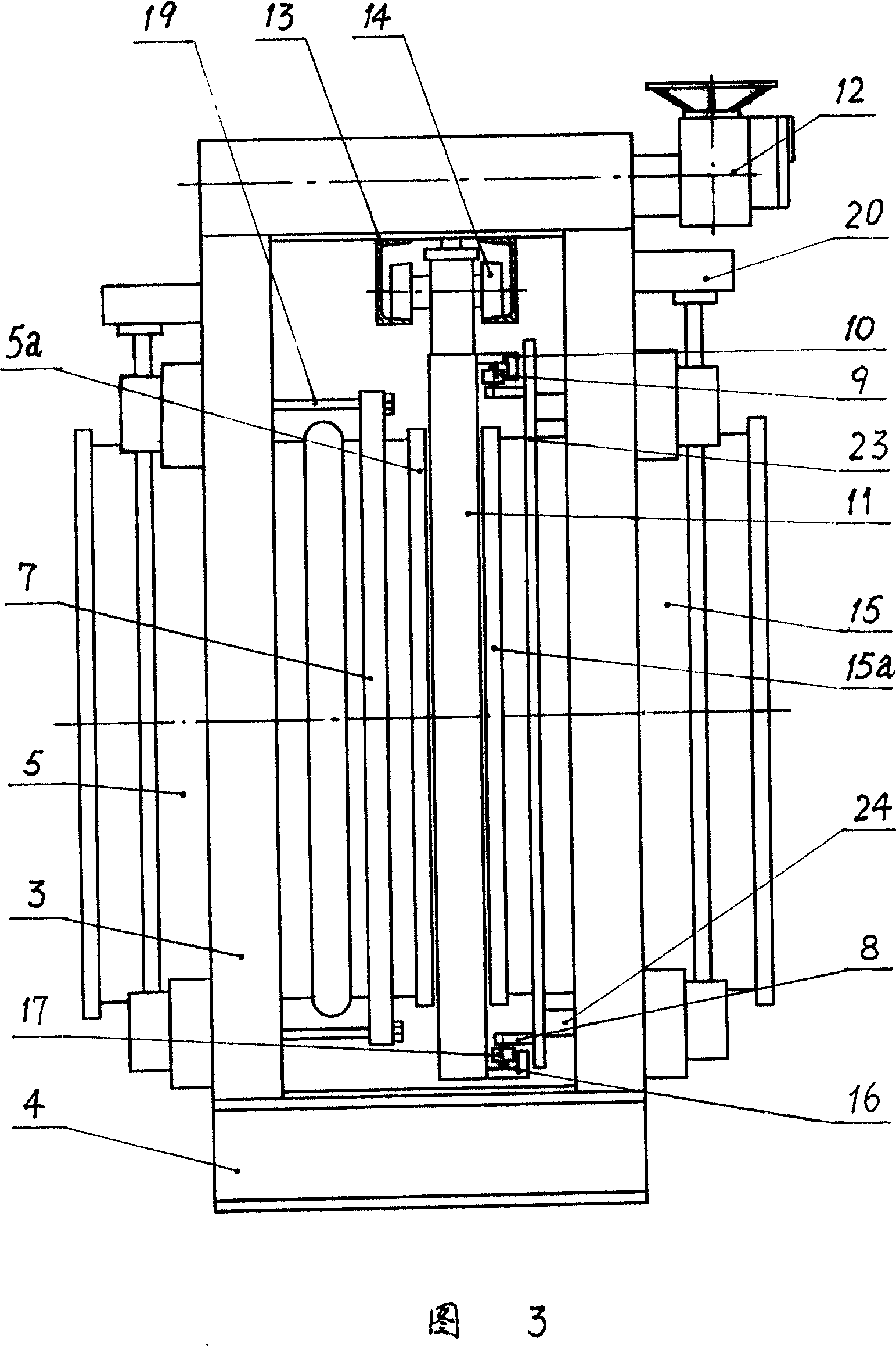
[0031] As shown in FIG. 3 , the basic structure of this embodiment is exactly the same as that of Embodiment 1, except that the pressure-bearing translation mechanism of the valve plate is different. The pressure-bearing translation mechanism of the valve plate in this embodiment is a movable frame plate 23 sleeved on the fixed valve body 15, and a horizontal plate 8 extending toward the direction of the valve plate is respectively connected to the movable frame plate and the lower side. A number of vertical shafts are respectively connected to the top, and rollers 9 and 17 are sleeved on the vertical shafts; an upper corner plate 10 and a lower corner plate 16 are respectively connected on the upper and lower frames of the valve plate 11, and the horizontal plate surfaces of the upper and lower corner plates span the rollers 9 , 17; the vertical plate surface of the upper gusset 10 is positioned between the movable frame plate 23 and the roller 9, and the vertical plate surfac...


PUM


Abstract

The invention relates ton a full-seal large-pressure differential glasses valve which uses valve to separate or press the sealing face of valve base, wherein the front and back ends of the main valve box are connected with a stable valve and a movable valve with a corrugated tube, two sides of the main valve box are connected whit a sub valve box, a valve plate with through hole ring and blind hole ring is arranged between the stable valve and the movable valve, a valve plate via a plurality of suspending wheels through at the upper part is suspended on a track at the top of the main valve box, a valve plate press release device is mounted on the main valve box and the movable valve, the top of the main valve box and the valve plate is mounted with a valve plate transverse device, and the main valve box is mounted with a valve plate bearing transverse device. The invention can start and close in pressure with confirmed normal medium pressure to cut off and connect the gas medium in tube.

Description

technical field [0001] The invention relates to a valve with a flat sealing surface, in particular to a fully-enclosed large-pressure-difference opening-and-closing spectacle valve which separates or compresses the sealing surface of a valve seat through the movement of a valve body. Background technique [0002] In the large and medium-sized gas pipelines of iron and steel and metallurgical enterprises, two-stage valves are currently used to shut off the gas medium in the pipeline. The pre-stage valves generally use disc valves, and the post-stage valves usually use spectacle valves (also known as "plate valves" or "flap valves"). The butterfly valve of the front stage can be opened and closed under pressure, but its sealing performance is poor; the spectacle valve of the latter stage cannot be opened and closed under pressure, but its sealing performance is good. Therefore, for the normal use of gas pipelines and to prevent gas leakage, two-stage valves have to be used: t...

Claims


Application Information

Patent Timeline
Patent Type & Authority Applications(China)
IPC IPC(8): F16K3/20
Inventor 邢建栋邢毅栋
Owner 邢建栋
Why Eureka
Try Eureka