
Laser resonance cavity of high-power and large-energy low-rank mode output

A laser resonator, high-energy technology, applied in the field of lasers, can solve the problems that the laser resonator cannot achieve low-order mode output, laser beam mode distortion, etc., and achieve the effect of improving the application range and realizing low-order mode output.

Inactive Publication Date: 2007-08-15
石景林
View PDF0 Cites 2 Cited by
  • Summary
  • Abstract
  • Description
  • Claims
  • Application Information

AI Technical Summary

Problems solved by technology

In addition, the mismatch between the output mirror and the laser Gaussian beam characteristics will cause mode distortion of the laser beam, and eventually the laser resonator cannot achieve low-order mode output

Method used


Image

  • Laser resonance cavity of high-power and large-energy low-rank mode output
  • Laser resonance cavity of high-power and large-energy low-rank mode output
  • Laser resonance cavity of high-power and large-energy low-rank mode output

Examples


Embodiment Construction

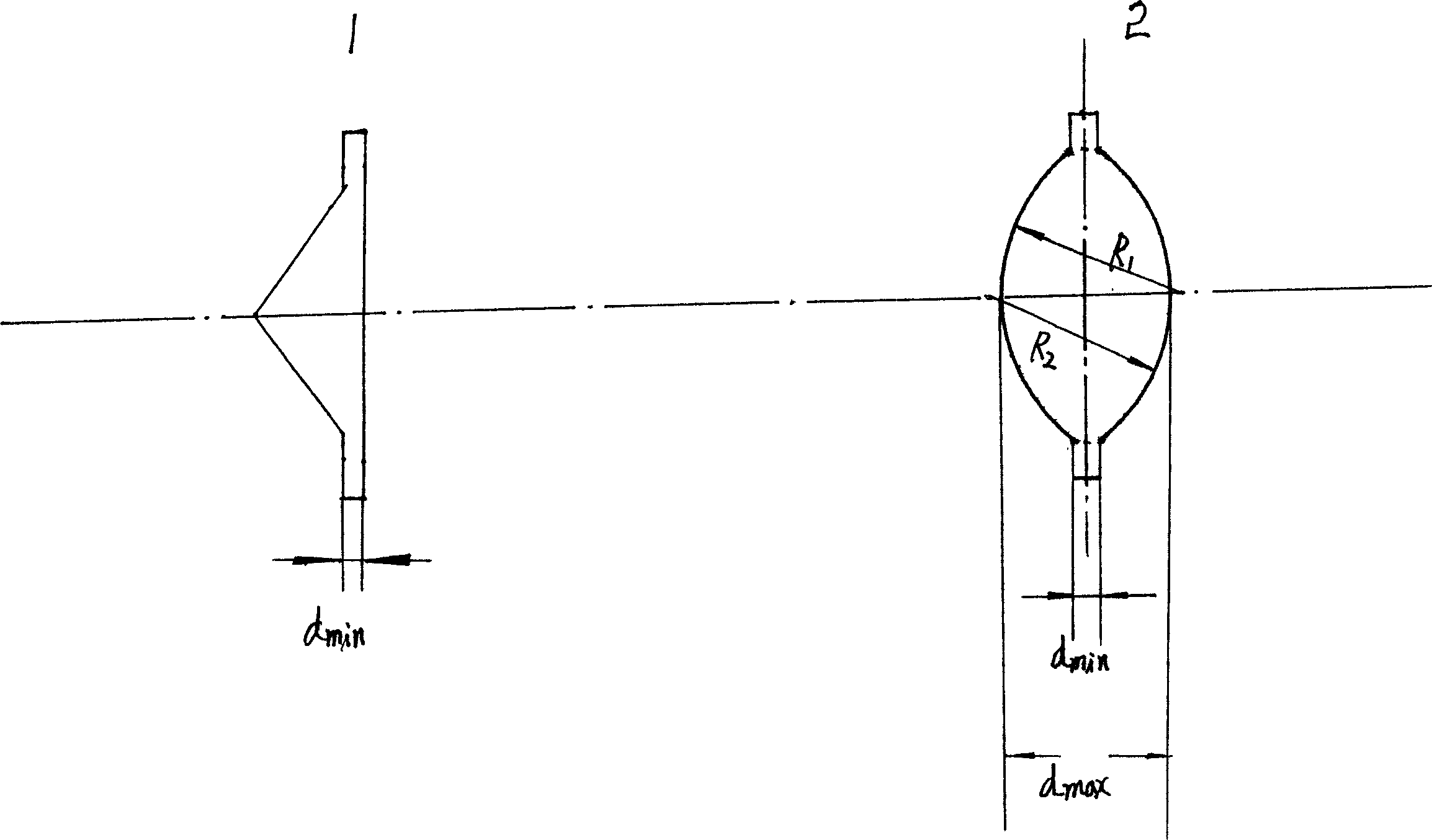
[0011] A laser resonator with high-power, high-energy and low-order mode output is characterized in that it is composed of a directional prism (1) and a symmetrical biconvex mirror (2), the directional prism (1) is a total reflection mirror, and the symmetrical biconvex mirror (2) is the output mirror.

[0012] The resonant cavity is designed according to the theoretical formula, which is characterized in that within the working range of the resonant cavity, the thermal deformation of the cavity mirror is basically less than λ / 10, the laser beam does not undergo mode distortion, and low-order mode output is realized in high-power and high-energy applications.

[0013]

[0014] Where a——material linear expansion coefficient μ——material Poisson’s ratio

[0015] E——Young’s modulus of the material K——The thermal conductivity of the material

[0016] beta 1 ——absorption coefficient of substrate material β 2 ——Coating absorption coefficient

[0017] P L ——Laser output po...


PUM


Abstract

The provided high-efficient high-power lower-mode laser cavity comprises: a total-reflection orientation prism (1), and a symmetrical biconvex mirror (2) as an output mirror matching with Gaussian beam characteristics. Wherein, it designs the cavity as theoretical formula, selects material with high thermal conductivity factor, and makes the beam cross-section area as large as possible. This invention overcomes defects in prior art, and can satisfy industrial request on superior laser processing technology.

Description

technical field [0001] The invention provides a laser resonator with high-power, high-energy and low-order mode output, belonging to the technical field of lasers. Background technique [0002] At present, both at home and abroad believe that the performance of the directional prism resonator is superior. Cheng Yong et al., Study on the characteristics of directional prism resonator, China Laser 2000, V01.A27, NO.6. The directional prism is a total reflection mirror, and one end of the laser rod is coated with a partial reflection film and the plane is an output mirror, forming a debugging-free resonant cavity. Since the resonant cavity of the directional prism is a parallel light field, the deflection of the prism does not cause the direction of the oscillating light in the cavity to change. The cavity allows a misalignment angle of up to ±20°, and the measured laser output energy does not vary by more than 5%. It has a high degree of misalignment resistance and mechanica...

Claims


Application Information

Patent Timeline
Patent Type & Authority Applications(China)
IPC IPC(8): H01S3/08
Inventor 石景林
Owner 石景林
Learn More