
Mixed three level resonance DC convertor and dual shift phase control method

A resonant DC, three-level technology, applied in the direction of converting DC power input to DC power output, adjusting electrical variables, control/regulation systems, etc., can solve the problem of increased stress circulation of power devices, reduced efficiency, and wide range of duty cycle changes and other problems, to achieve the effect of reducing the output filter and reducing the input current ripple

Inactive Publication Date: 2007-08-15
NANJING UNIV OF AERONAUTICS & ASTRONAUTICS
View PDF0 Cites 45 Cited by
  • Summary
  • Abstract
  • Description
  • Claims
  • Application Information

AI Technical Summary

Problems solved by technology

However, it adopts PWM control. When it is applied to the occasion with a wide input voltage range, the primary and secondary turns ratio of the transformer will become smaller, and the duty cycle will vary in a wide range, which will increase the stress of the power device and the circulating current in the circuit, resulting in the converter The design cannot be optimized, and the efficiency is reduced

Method used


Image

  • Mixed three level resonance DC convertor and dual shift phase control method
  • Mixed three level resonance DC convertor and dual shift phase control method
  • Mixed three level resonance DC convertor and dual shift phase control method

Examples


Embodiment Construction

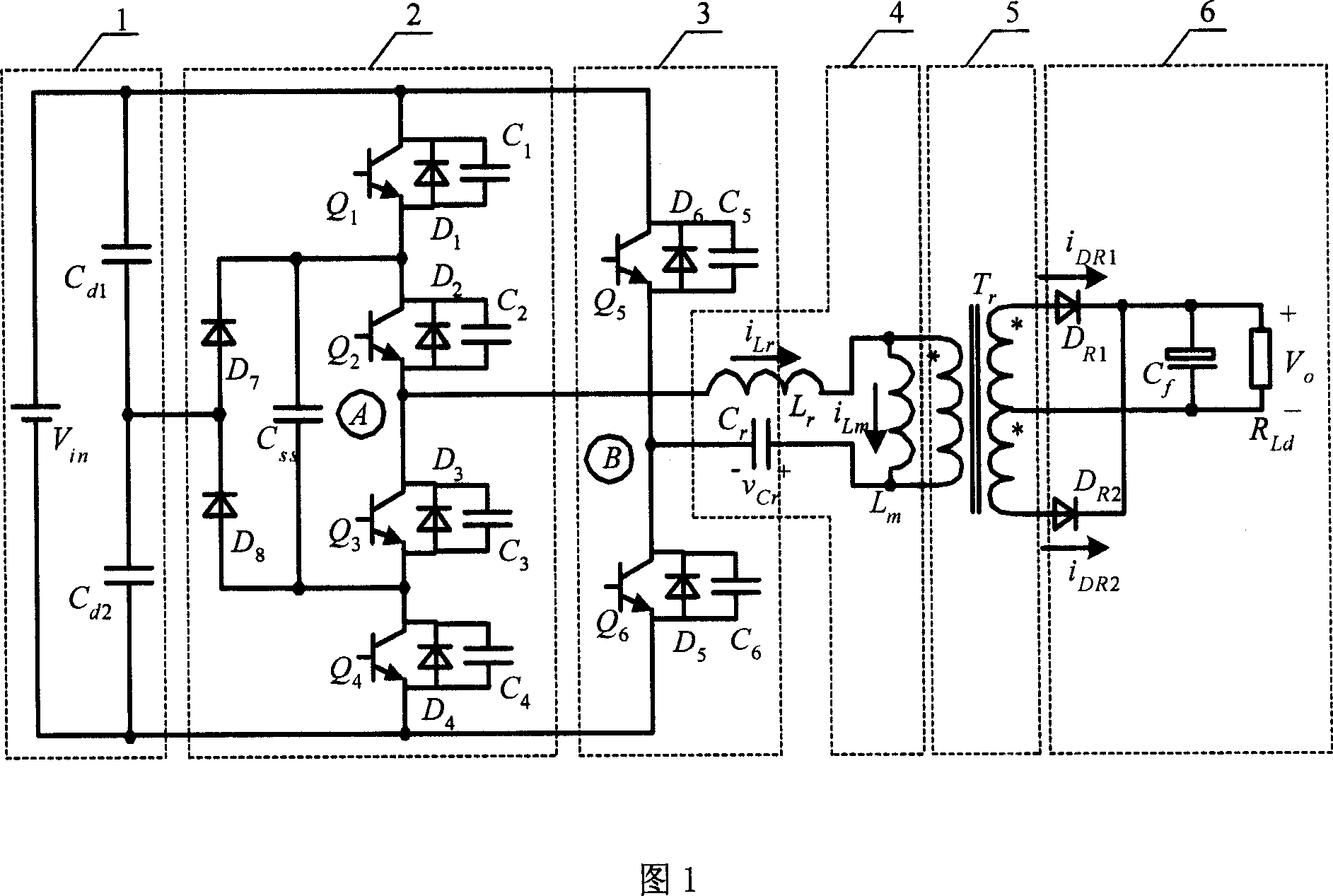
[0014] Describe the circuit composition structure of the present invention according to accompanying drawing 1.

[0015] Accompanying drawing 1 is the basic structure schematic diagram of the present invention, is made up of input voltage dividing capacitor circuit 1, three-level bridge arm 2, two-level bridge arm 3, resonant network 4, isolation transformer 5, rectification and filter circuit 6. where the voltage divider capacitor C d1 and C d2 The capacity is large and equal, and its voltage is the input voltage V in half of the V cdl =V cd2 =V in / 2, which can be regarded as a voltage of V in / 2 voltage source.

[0016] The three-level bridge arm consists of four switching tubes Q 1 , Q 2 , Q 3 , Q 4 , two freewheeling diodes D 7 and D 8 , flying capacitor C ss composed of four switching tubes Q 1 , Q 2 , Q 3 , Q 4 for MOSFETs. Flying capacitor C ss The role of the switch tube Q 1 , switch tube Q 4 with switch Q 2 , switch tube Q 3 The switching proce...


PUM


Abstract

The hybrid three-level harmonic dc converter comprises an input voltage-dividing capacitor (1), a three-level bridge arm (2) with voltage stress half of the input value, two-level bridge arm (3), a harmonic network (4), an isolation transformer (5), and a rectification filter circuit (6). Wherein, it applies dual shift-phase control strategy, all switch tubes can realize zero-voltage operation in full load range. This invention reduces both ripple of input current and filter output,, and can work in very broad input voltage range.

Description

1. Technical field [0001] The invention relates to a hybrid three-level resonant DC converter and a double-phase-shift control method, which belong to a DC converter of an electric energy conversion device. 2. Background technology [0002] With the continuous improvement of human living standards, the demand for energy has increased significantly. As a non-renewable energy source, fossil energy is becoming increasingly exhausted, and the environmental pollution it causes is becoming increasingly serious. Solar photovoltaic power supply and fuel cell power supply are used more and more as green new energy power supply methods. Their biggest advantage is low noise and no pollution to the environment. Therefore, the research on solar photovoltaic power supply system and fuel cell power supply system is of great significance to reduce environmental pollution and solve energy crisis. [0003] The biggest feature of fuel cells and solar cells is that their external characteris...

Claims


Application Information

Patent Timeline
IPC IPC(8): H02M3/28H02M3/335H02M7/5387
CPCY02B70/1491Y02B70/10
Inventor 金科阮新波
Owner NANJING UNIV OF AERONAUTICS & ASTRONAUTICS
Features
  • Generate Ideas
  • Intellectual Property
  • Life Sciences
  • Materials
  • Tech Scout
  • Unparalleled Data Quality
  • Higher Quality Content
  • 60% Fewer Hallucinations
Learn More