
Method of manufacturing vibration plate for speaker and vibration plate for speaker

A manufacturing method and technology of vibration plates, which are applied in the manufacture of vibration plates for loudspeakers and the field of vibration plates for loudspeakers, can solve problems such as delamination between layers, decline in sound characteristics of loudspeakers, and long-term

Inactive Publication Date: 2007-08-15
PIONEER CORP +1
View PDF1 Cites 15 Cited by
  • Summary
  • Abstract
  • Description
  • Claims
  • Application Information

AI Technical Summary

Problems solved by technology

[0006] However, in the manufacturing method of the speaker diaphragm of the above-mentioned multilayer structure, after papermaking is performed on different forming materials in advance, for example, after applying an adhesive and bonding them together by a pressing device, bonding is required. agent coating process and press molding process, etc.
In addition, these processes take a relatively long time
In addition, in order to carry out these processes, relatively large-scale equipment is required
[0007] In addition, in the above-mentioned production method, since each layer of papermaking is dehydrated in advance and then overlapped, for example, in the case of lamination of fiber layers, the bonding between the layers is relatively weak, and problems such as delamination between layers may occur.
If problems such as delamination occur, there is a problem that the acoustic characteristics of the speaker will be significantly reduced

Method used


Image

  • Method of manufacturing vibration plate for speaker and vibration plate for speaker
  • Method of manufacturing vibration plate for speaker and vibration plate for speaker
  • Method of manufacturing vibration plate for speaker and vibration plate for speaker

Examples


no. 1 approach

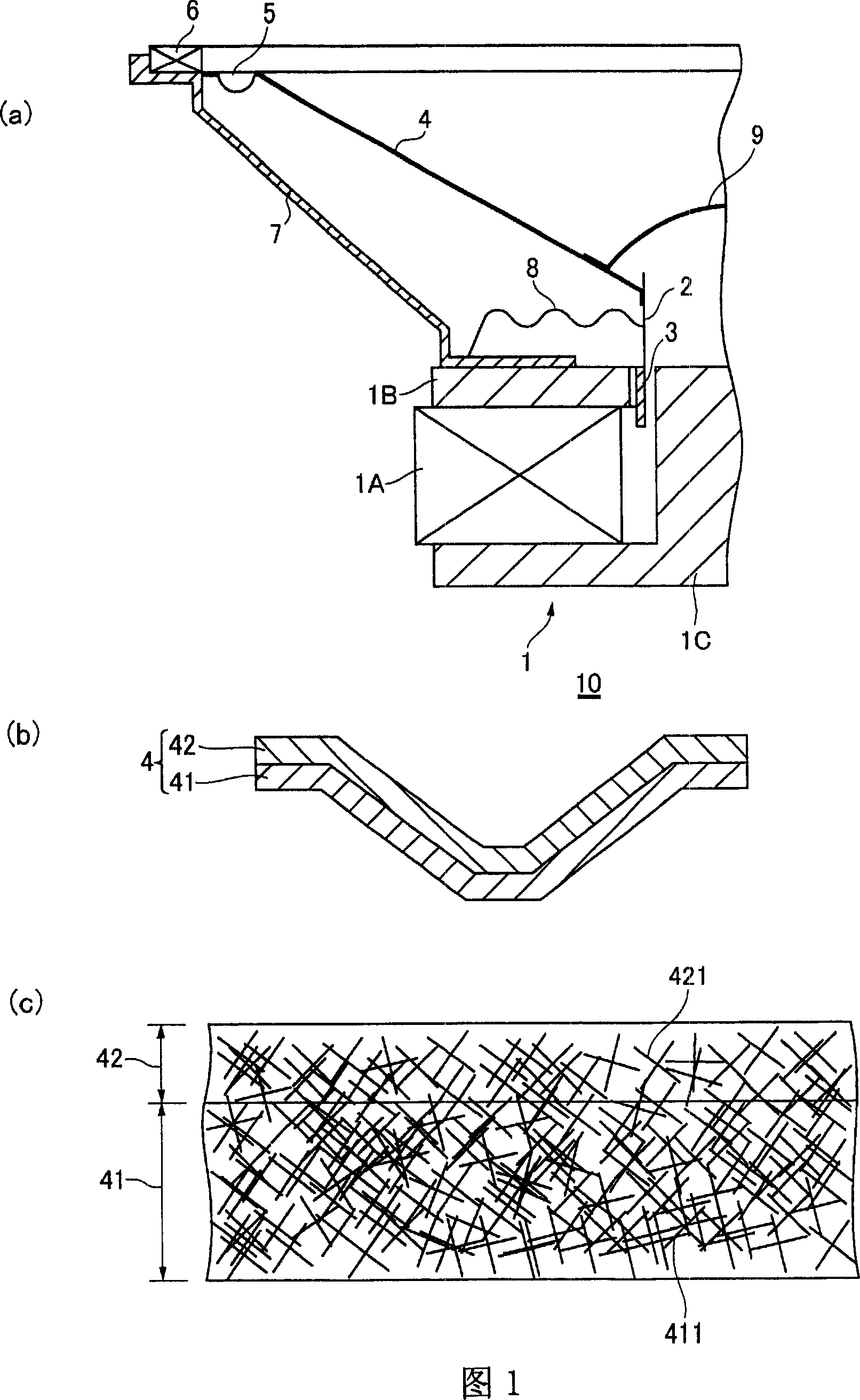
[0062] FIG. 1 is a diagram illustrating a speaker diaphragm according to a first embodiment of the present invention. FIG. 1( a ) is a half-sectional view illustrating a speaker device using a speaker diaphragm according to a first embodiment of the present invention. FIG. 1( b ) is a cross-sectional view for explaining the speaker diaphragm shown in FIG. 1( a ). FIG. 1( c ) is an enlarged cross-sectional view for explaining the speaker diaphragm shown in FIG. 1( b ).

[0063] As shown in FIG. 1( a), a speaker device 10 using a speaker diaphragm according to the first embodiment of the present invention has: a magnetic circuit 1 formed by a magnet 1A, a plate 1B, and a yoke 1C; a voice coil 3 configured In the magnetic gap of the magnetic circuit 1, and wound on the voice coil bobbin 2; The outer peripheral edge of the speaker diaphragm 4 is fixed to the speaker frame 7 via the edge portion 5 and the gasket 6 . Voice coil bobbin 2 is fixed to speaker frame 7 via damping mem...

no. 2 approach

[0101] FIG. 10 is a diagram for explaining a method of manufacturing the speaker diaphragm 4b according to the second embodiment of the present invention. Descriptions of the same configuration, operation, and the like as those of the first embodiment are omitted.

[0102] The manufacturing method of the speaker diaphragm 4b of the present embodiment is to manufacture the speaker diaphragm 4b by forming it by a drying method after papermaking. Specifically, as shown in FIG. 10, for example, in the drying chamber 600, the first vibration plate layer 41b and the second vibration plate layer 42b stacked by the papermaking described above are arranged on a mold 63 having a hollow portion 631, and are While being sucked by a vacuum pump 632 , it is dried by a heating device 64 such as a gas furnace arranged above the mold 63 . In this embodiment, the diaphragm 4b for speakers is produced by drying only without pressurization.

[0103] Next, a specific method of manufacturing the ...


PUM


Abstract

The invention provides a method for manufacturing diaphragm for loudspeaker and diaphragm for speaker. The object of the invention is to manufacture diaphragm for loudspeaker with plural structure by paper-making without coating binder, to prevent stripping among vibrating board layers, and to manufacture the expected vibrating board for loudspeaker by stacking the materials with different characteristics with paper-making. The method comprises: injecting the suspension containing forming material of the vibrating board layer by a means of liquid layer spaced without the forming material of the vibrating board into the common paper-making pool in order; operating the paper-making to the suspension in order to stack plural vibrating board layer. Compared to the present method of binding by binder, the invention can manufacture plural layer diaphragm for loudspeaker by paper-making without coating binder after presetting paper-making to respective vibrating board layer.

Description

technical field [0001] The present invention relates to a method for manufacturing a loudspeaker diaphragm and the loudspeaker diaphragm. Background technique [0002] In general, if a speaker device has acoustic characteristics such as high sensitivity, a wide reproduction frequency band, and low harmonic distortion, it can be said that the performance of the speaker device is high. Therefore, among the main components of the speaker device, it is preferable that the diaphragm for a speaker, which greatly affects the above-mentioned characteristics, have the following characteristics: low material density, high Young's modulus, moderate internal loss, and the like. Furthermore, for example, speaker devices for in-vehicle use or outdoor use, speaker devices for portable information processing devices or mobile information processing devices, etc., it is desired to obtain a speaker device that can be used in significantly more ways, and has durability, heat resistance , wate...

Claims


Application Information

Patent Timeline
Patent Type & Authority Applications(China)
IPC IPC(8): H04R31/00H04R7/02
Inventor 佐藤喜浩菅野芳尚川田一春
Owner PIONEER CORP
Learn More